Introduction: Polar CNC Plotter
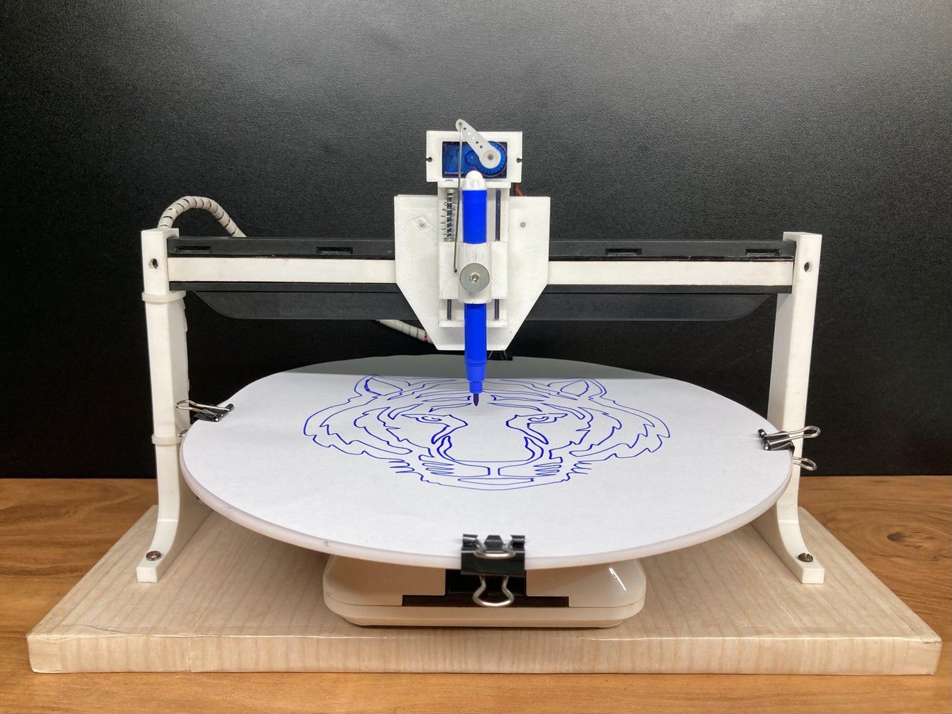
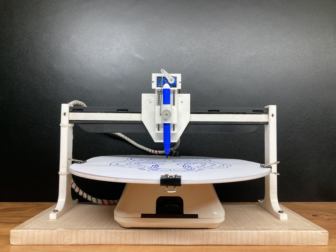


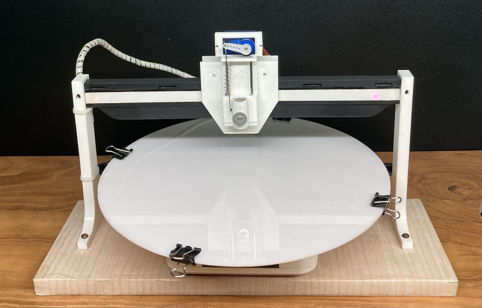
In this Instructable, I will show you how to make your own Polar CNC Plotter. The materials used for this project are old Wi-Fi camera, discarded materials from my old laser printer, Pinch rollers from old Tape recorders, 3D printed parts and wooden piece. I also used cheap 28byj-48 Stepper motors to make it cost effective. This plotter is very compact, light in weight and looks cool. Let’s get started!
Supplies
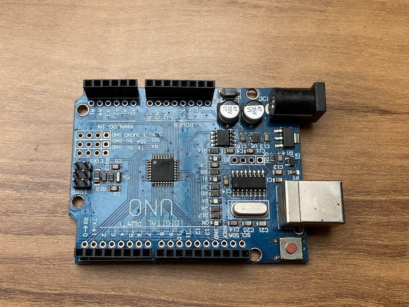
- Arduino Uno (1pcs)
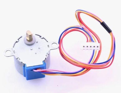
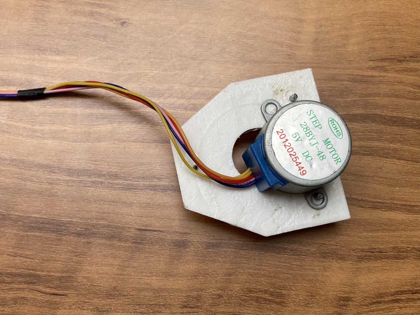
- 28byj-48 Stepper motor (2pcs)
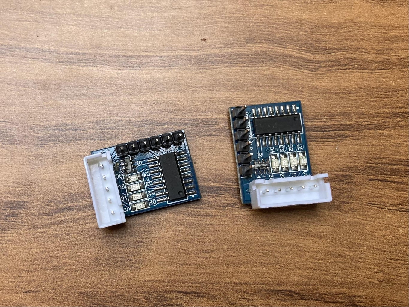
- ULN2003 stepper motor driver (2pcs)
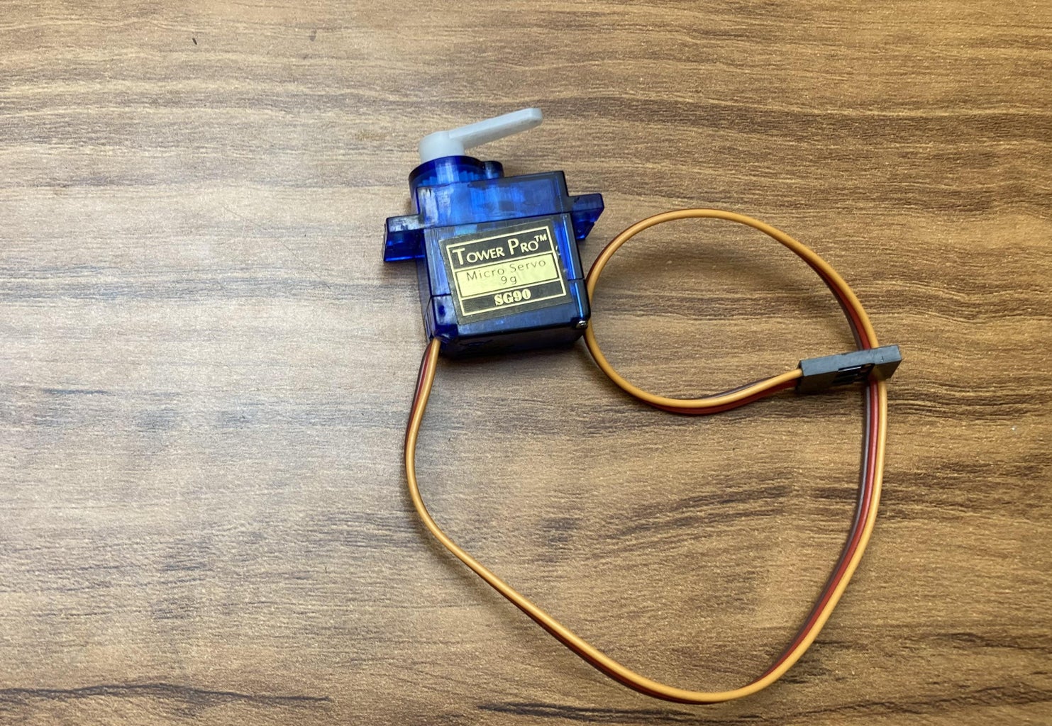
- Servo motor (1pcs)
- Cable zip ties (2 pcs)
- Acrylic circular sheet (20 cm diameter)
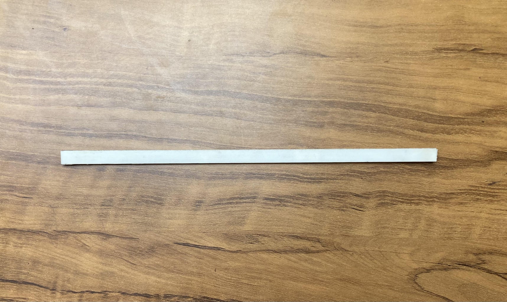
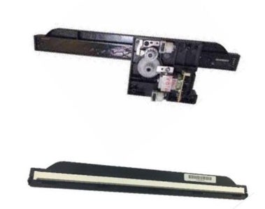
- Old Scanner head of LaserJet printer (used as rail track)
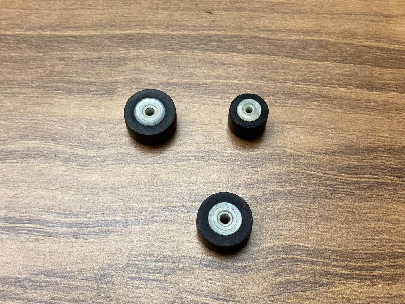
- Pinch rollers from old Tape recorders (3pcs)
- Wires
- 3D printed parts
- Old wireless camera
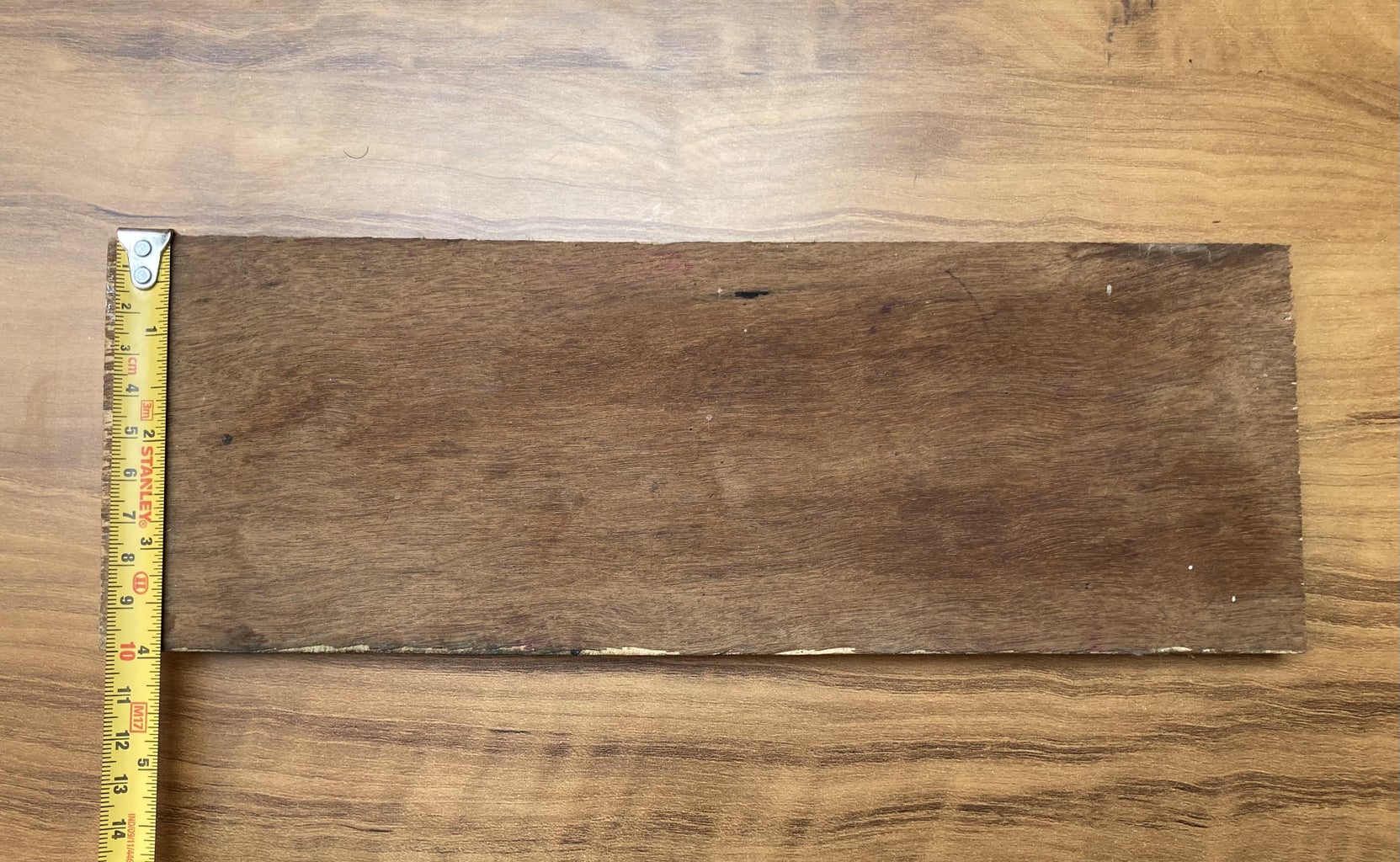
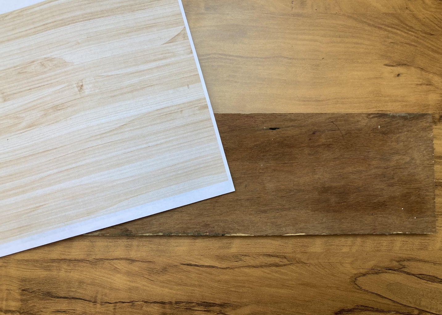
- Wood piece(29cm X 10cm X 1.2cm)
- Super glue
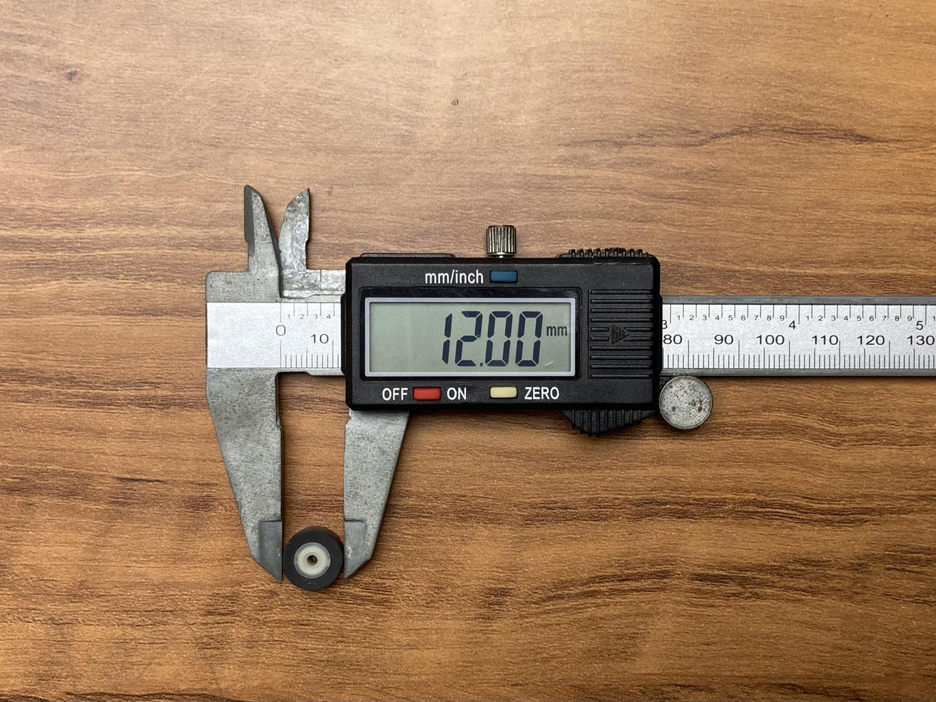
- Rubber sealing washer
- Straw (spiral cable wrap/ cable sleeve)
- LED light strip
- Double sided foam tape
- Screws
- Wood texture colored paper
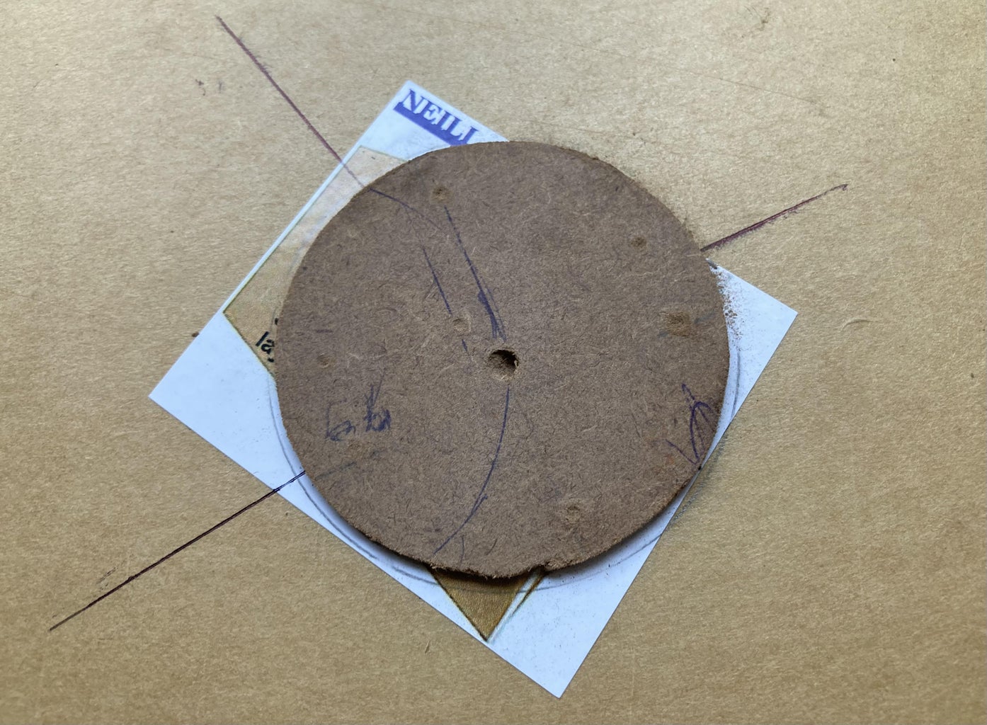
- Cardboard sheet
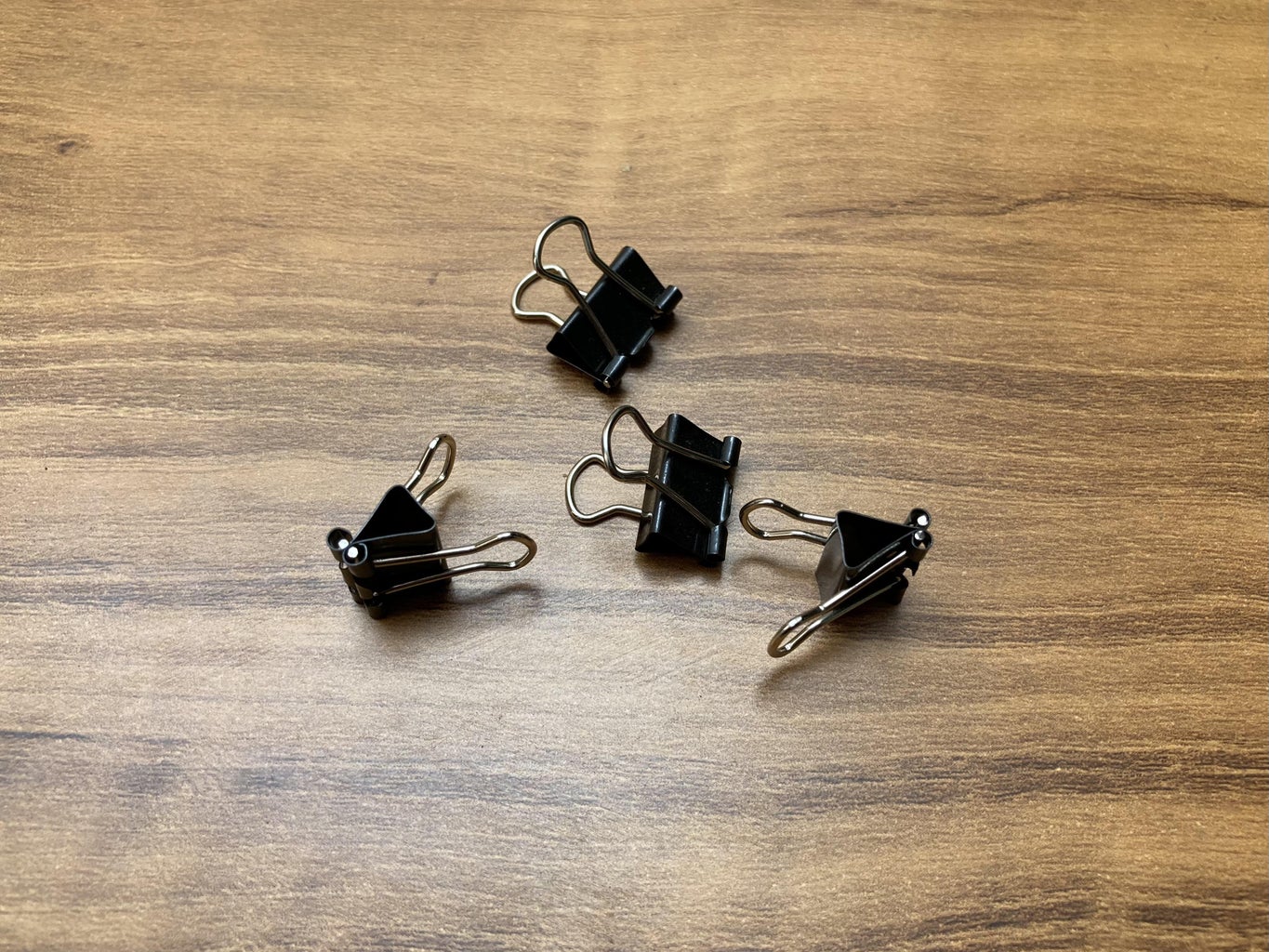
- Paper clips
- Color pens
- A4 White paper sheets
- Jumper wires
- Pen Spring
- Smooth steel rods (1.5mm dia., 65mm length- 2pcs)
- Heat shrink sleeve tubes (1mm dia.)
- 5V DC Power Jack Socket Female (1pcs)
Tools used:
- 3D printer
- Scissors
- Screw driver set
- Soldering iron
- Vernier Caliper Digital
- Measuring tape/ scale
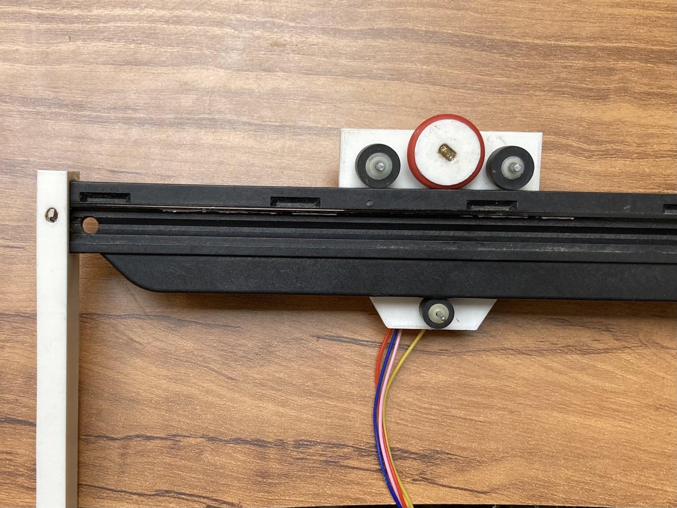
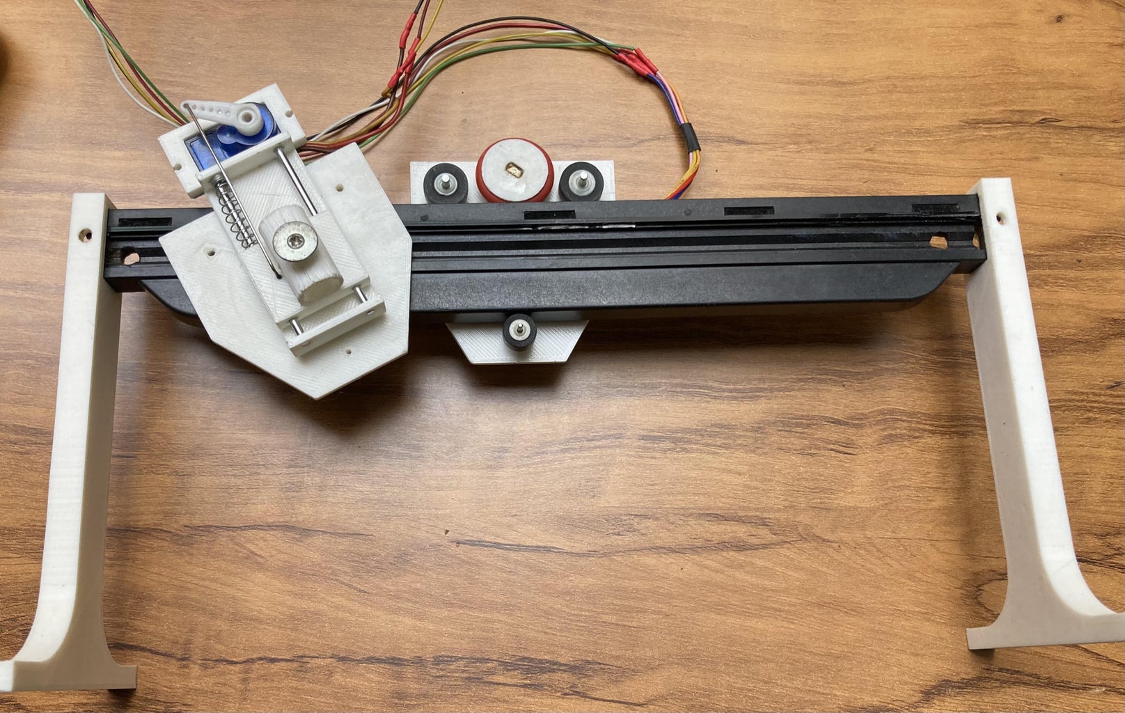
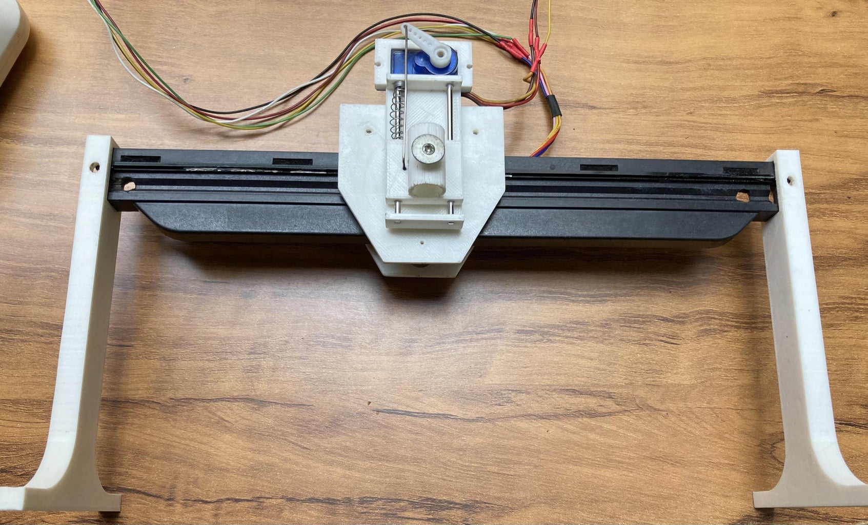
Step 1: Build Linear X-Axis
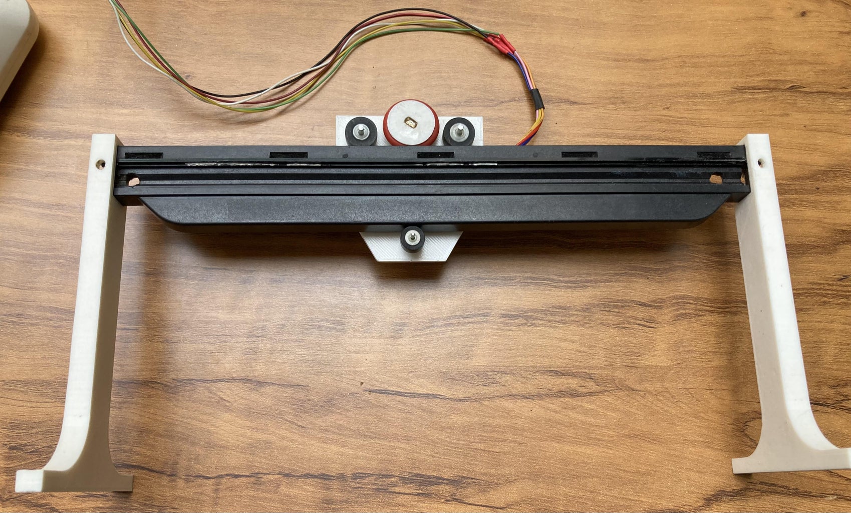
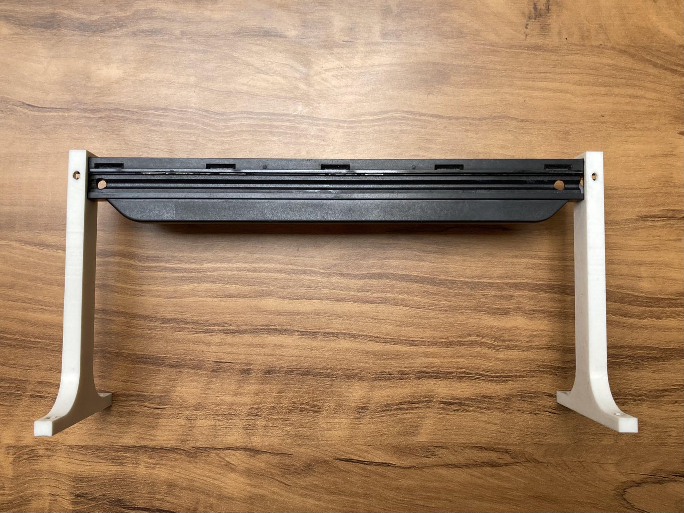
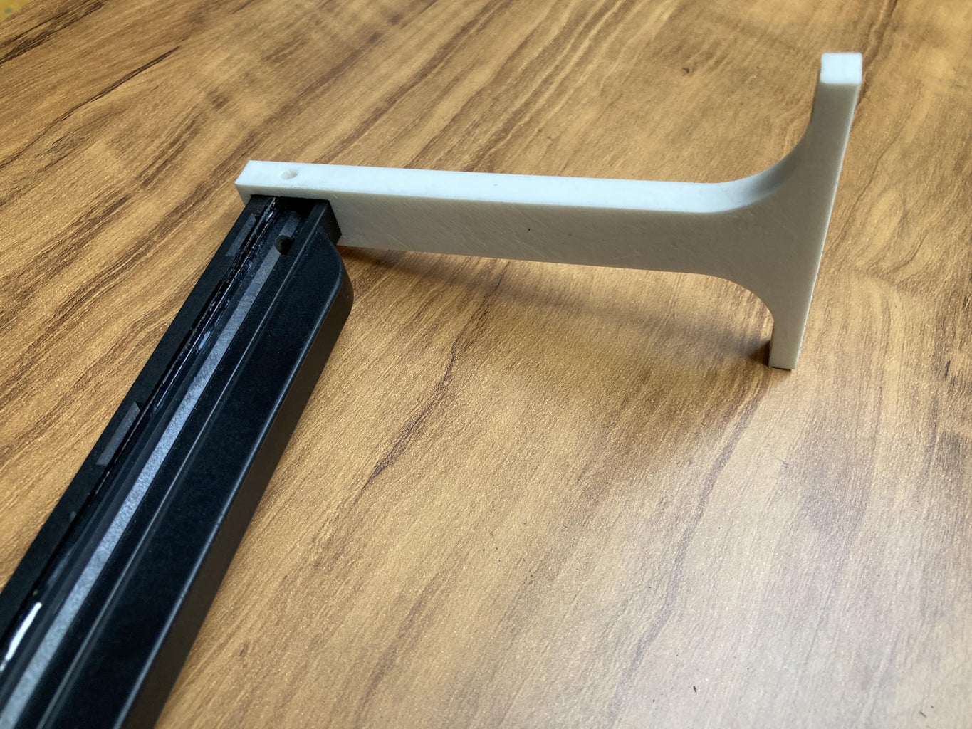

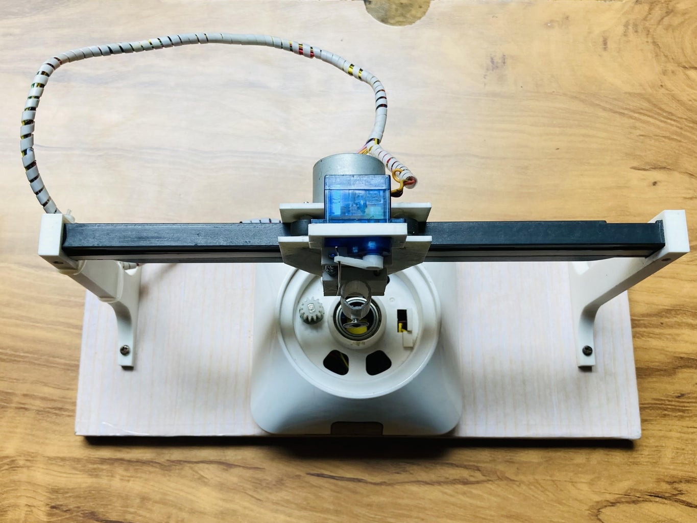
Linear X-axis consists of a Old Scanner head of LaserJet printer (used as a rail track) mounted on the 3D printed supports on either ends.
A LED Strip of 3 LEDs putted in the scanner head which is also powered by the same power source as that of servo motor.
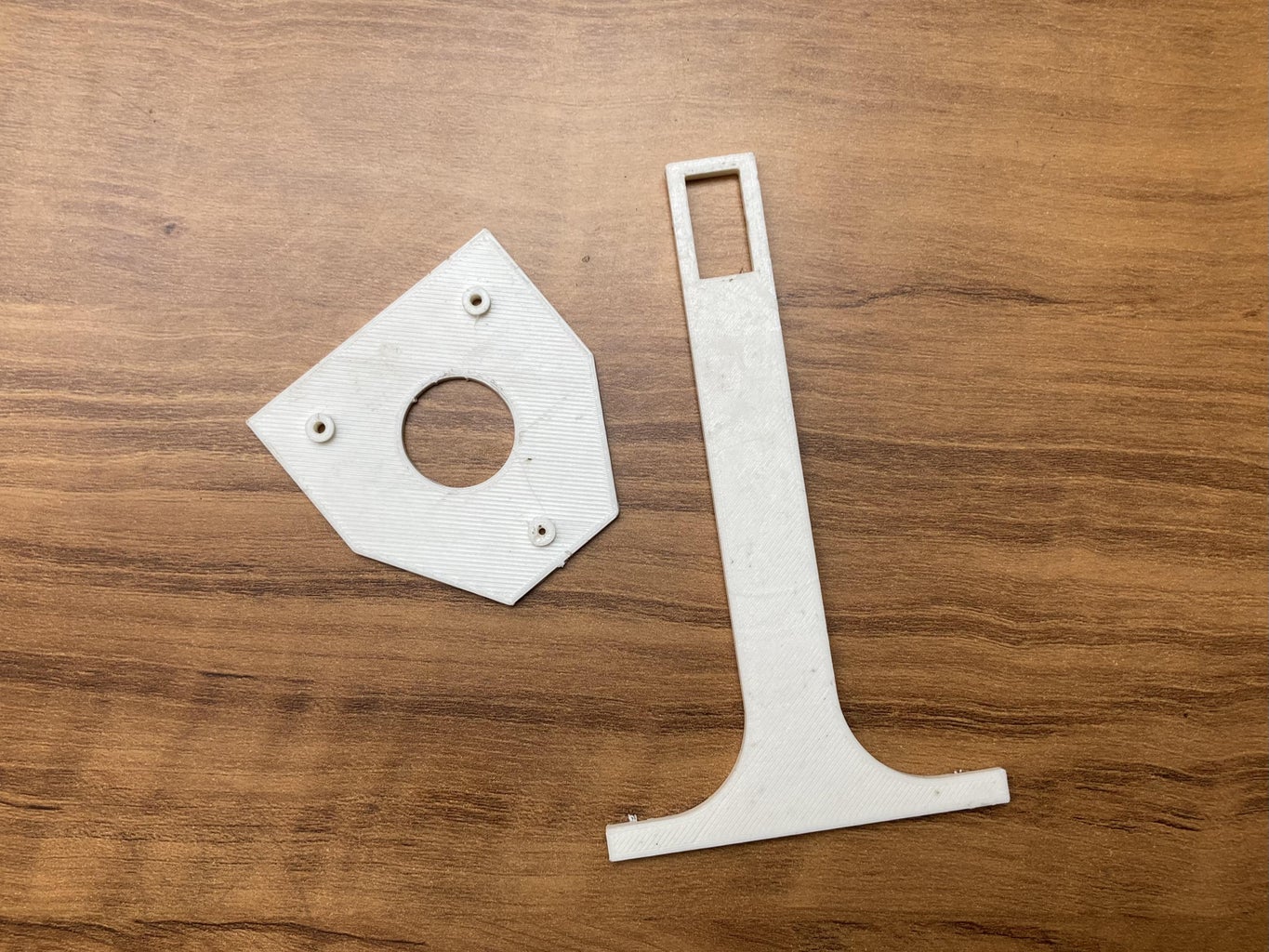
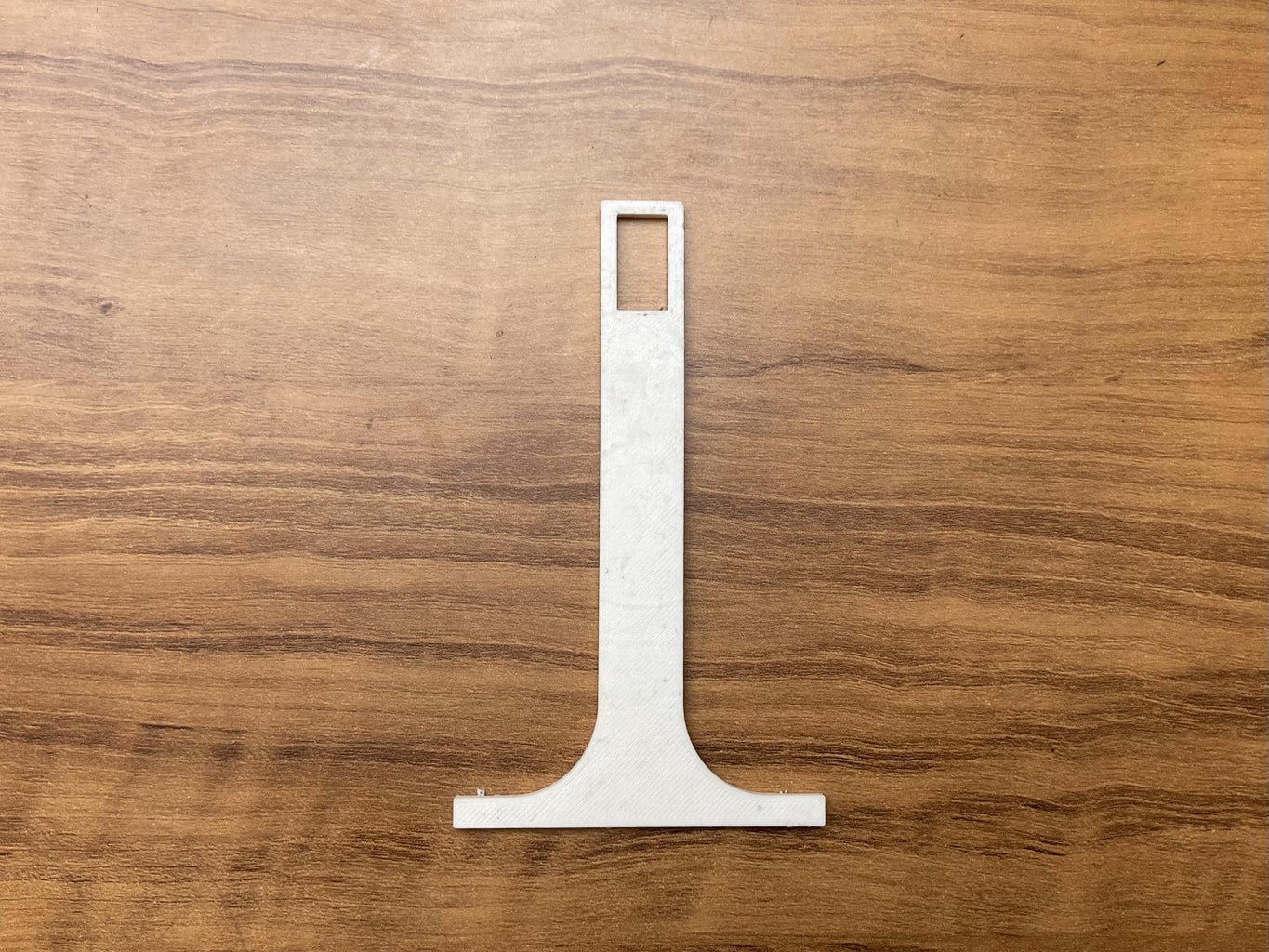
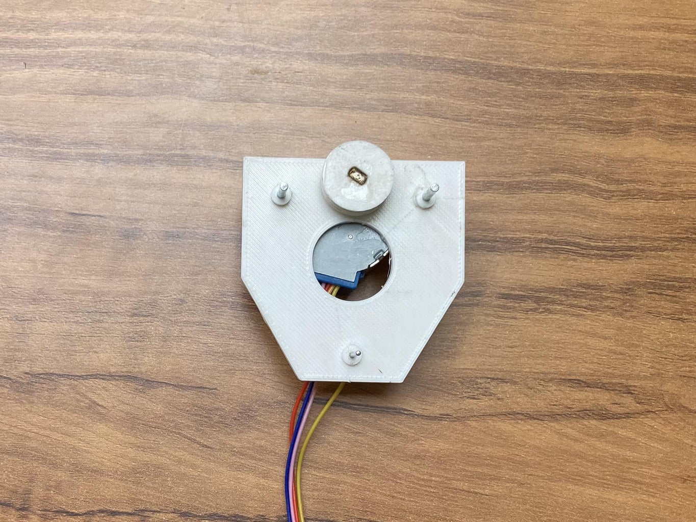
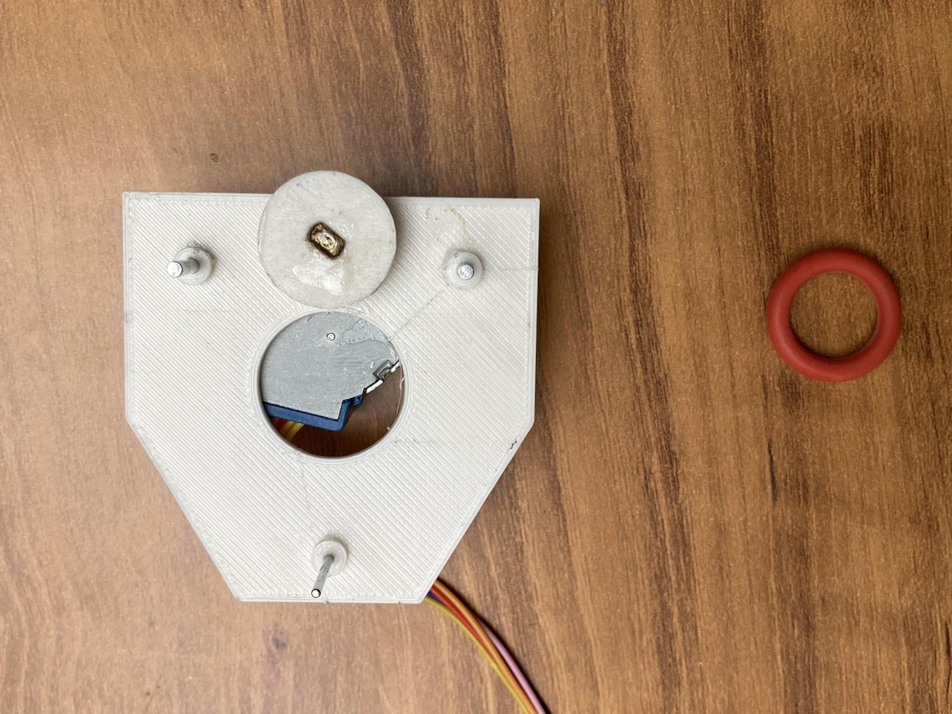
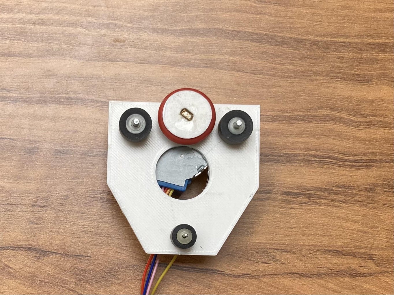
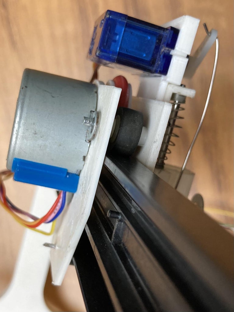
A set of parts are designed and 3D printed to hold Stepper motor and servo motor together which can travel linearly on the rail track with the help of 3 pinch rollers, which I got from old tape recorders.
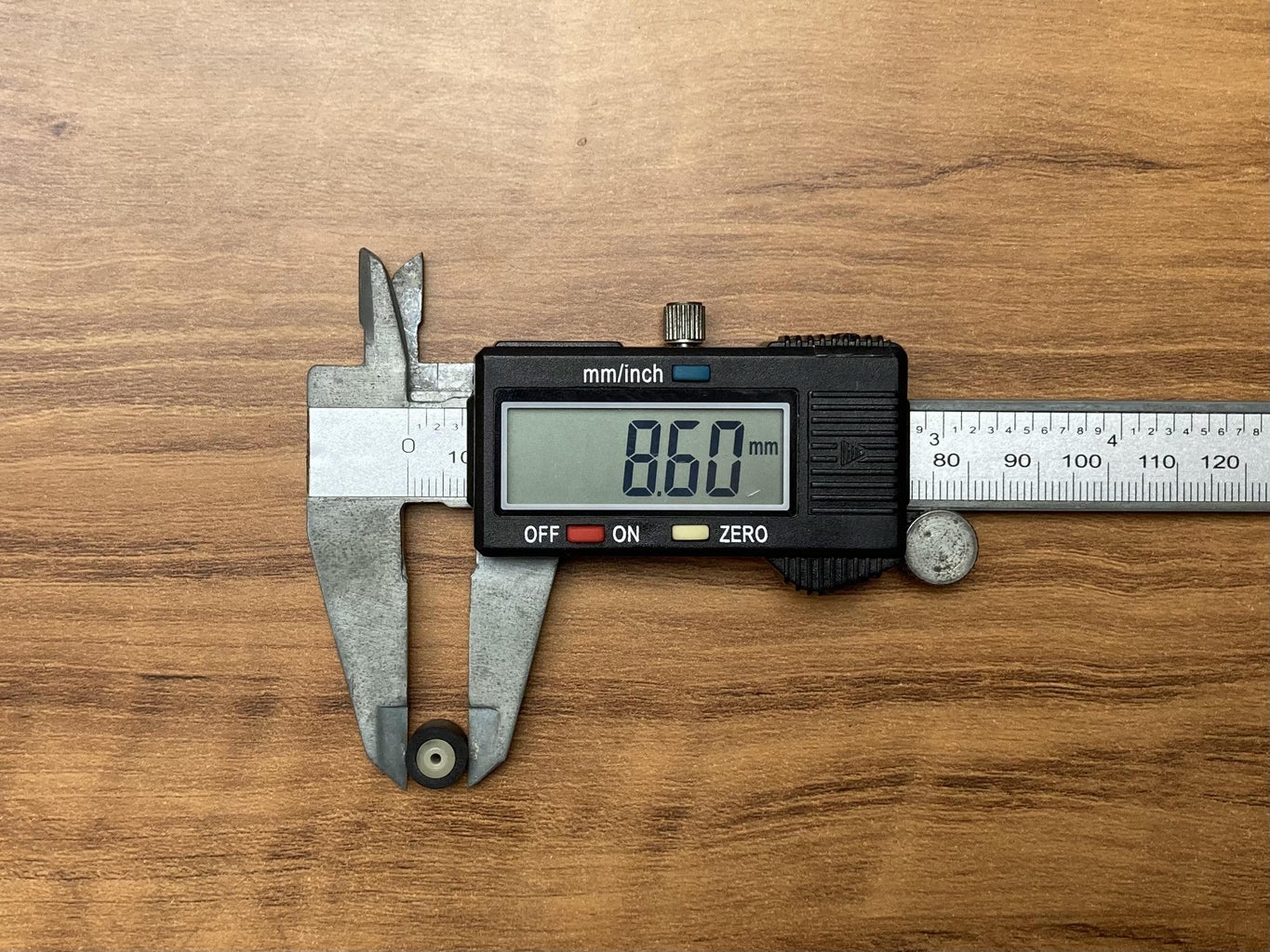
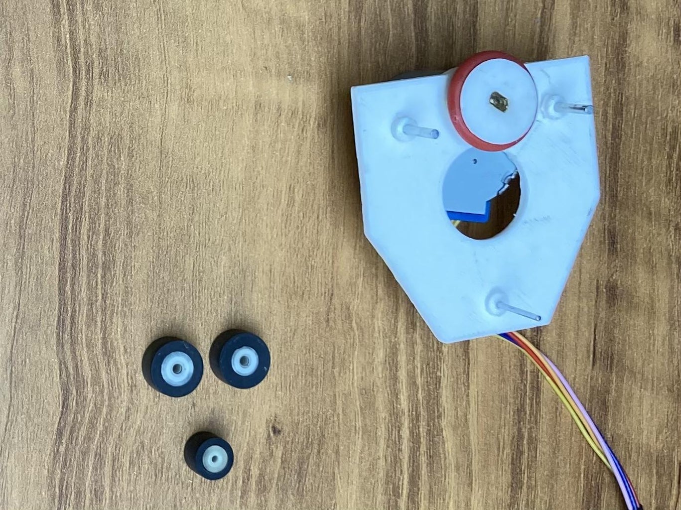
A 3D printed pulley is attached to the shaft of stepper motor with the help of glue. On the pulley a rubber sealing washer is attached, which help in gripping and rolling on the rail track.
The whole set is hold together with the help of shafts of pinch rollers.
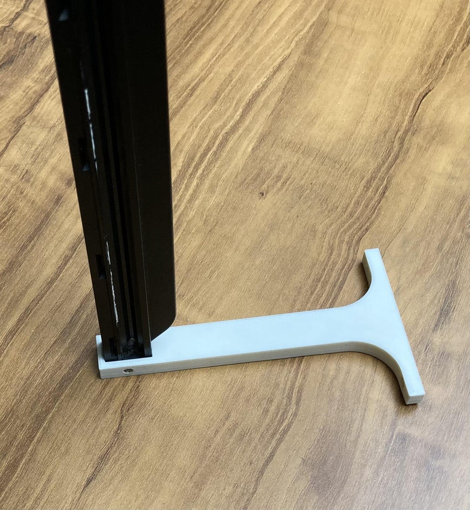
The 3d printed supports are attached to the wooden piece (base) with the help of self drilling screws.
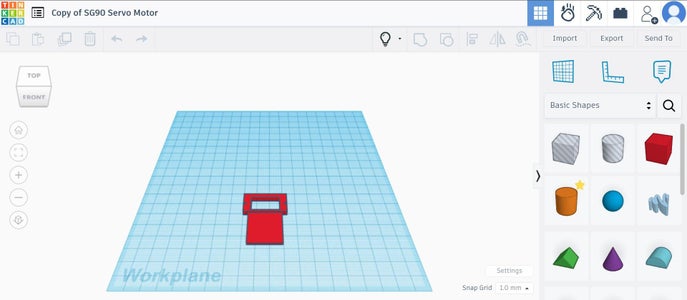
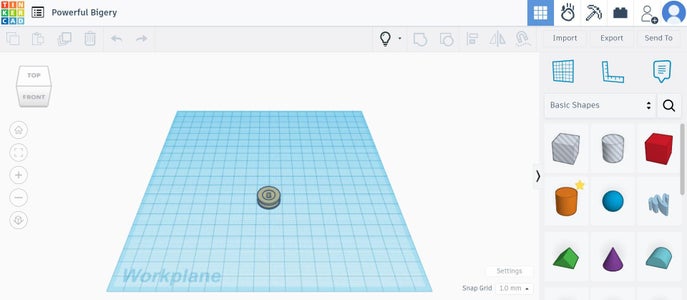
You can download STL files of 3D printed parts provided at the end of this tutorial.
Step 2: Build Rotary Y-Axis
Y-axis rotary table consists of:
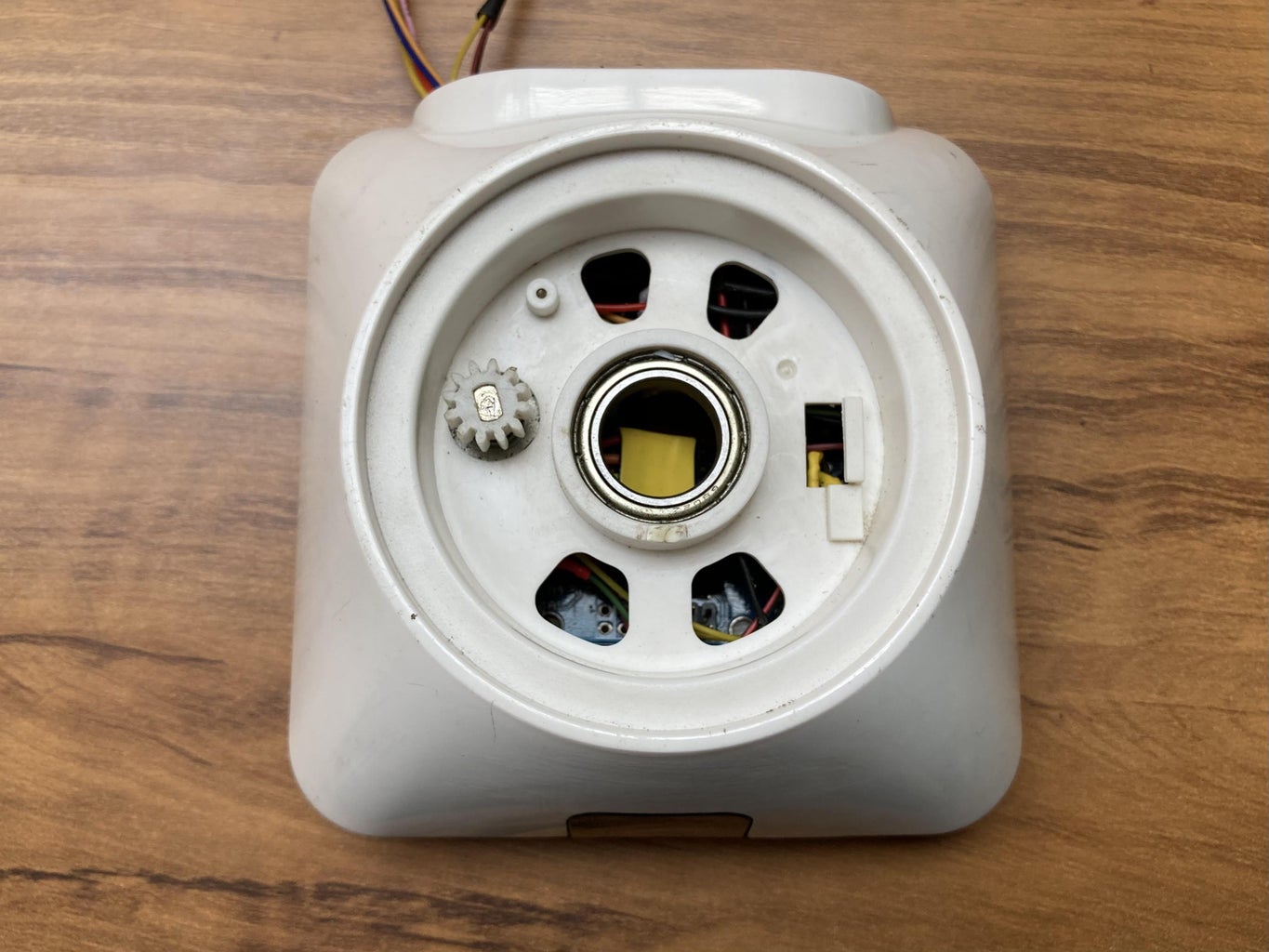
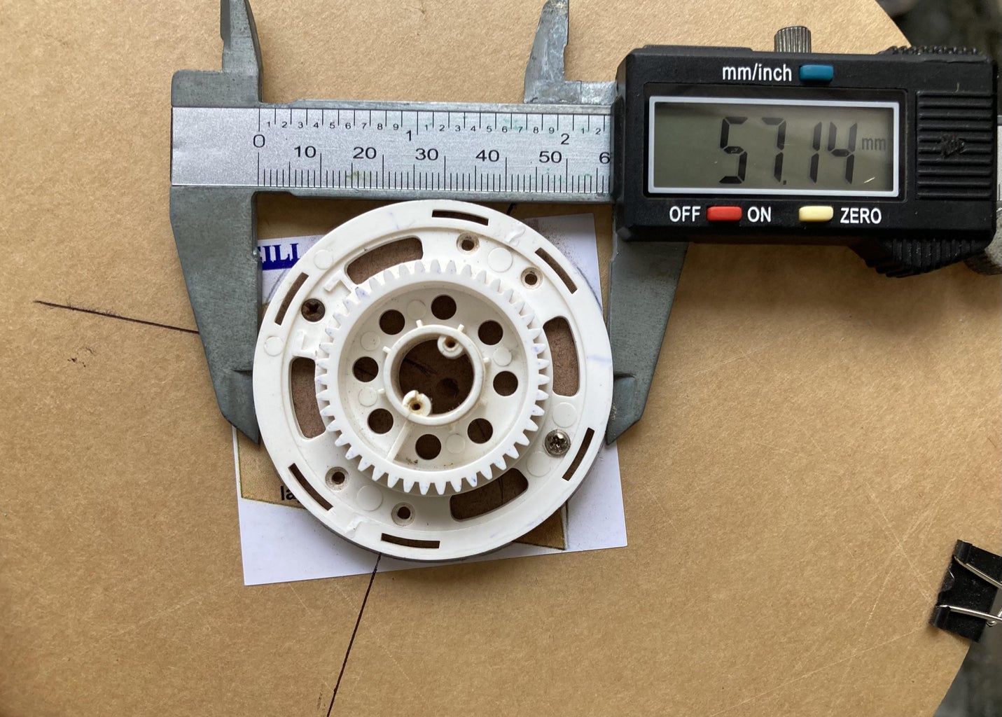
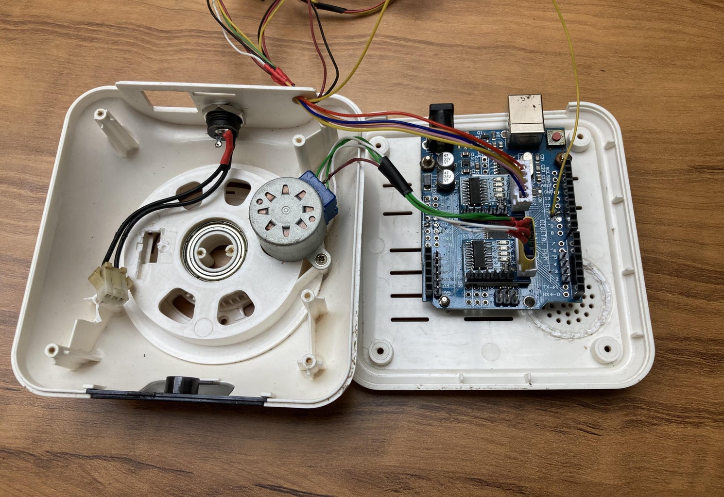
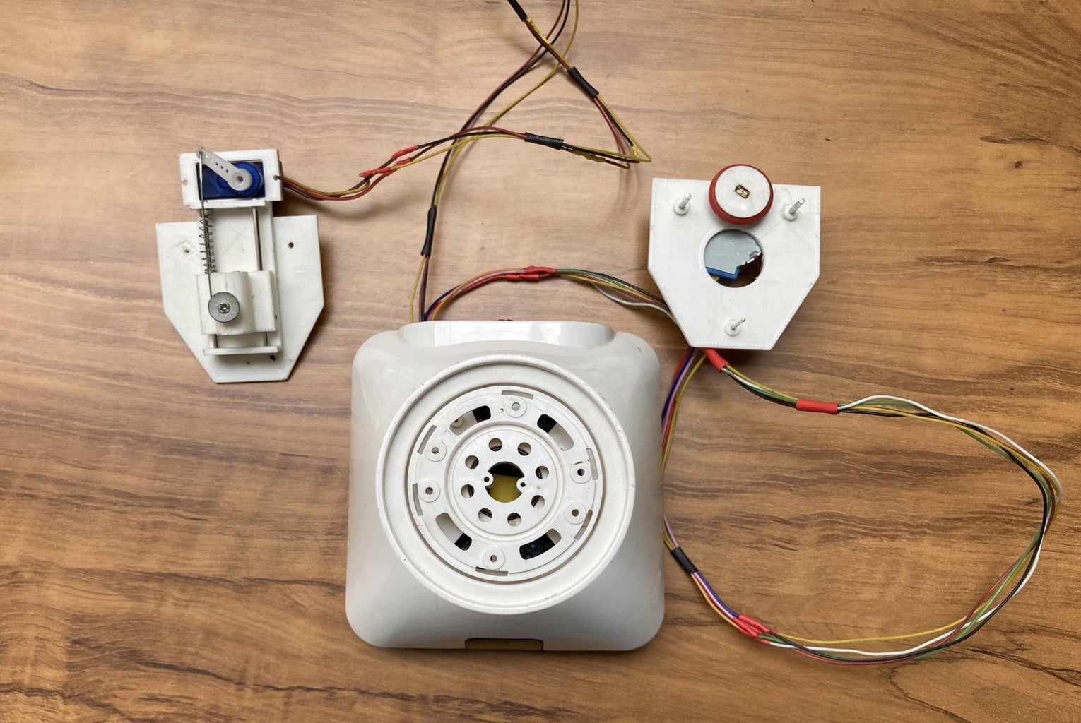
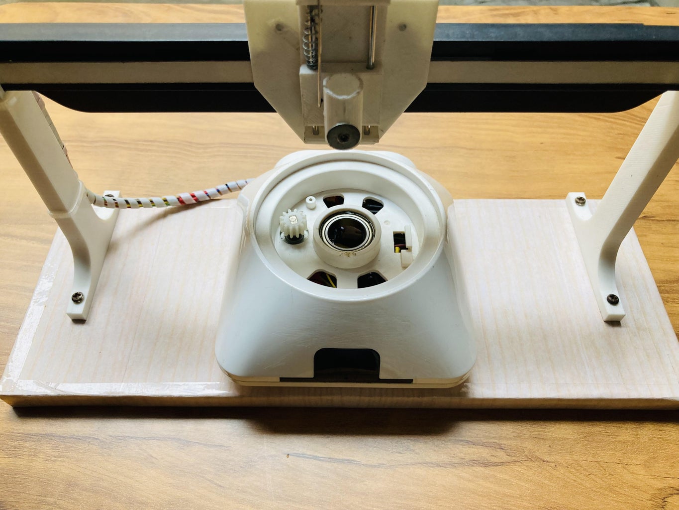
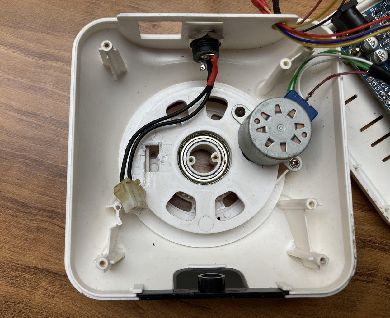
Bottom part of old Wi-Fi camera already consists of one unipolar stepper motor having a driver gear (teeth) meshing with a driven gear (teeth) so I need only one new unipolar stepper motor.
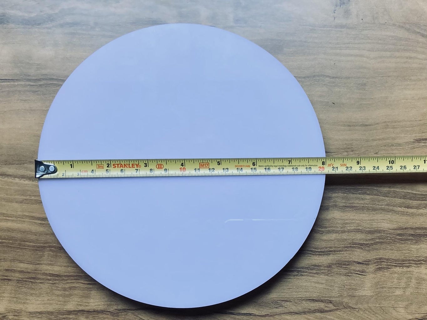
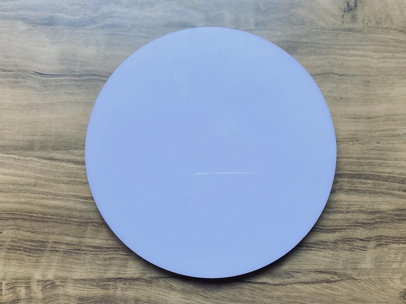
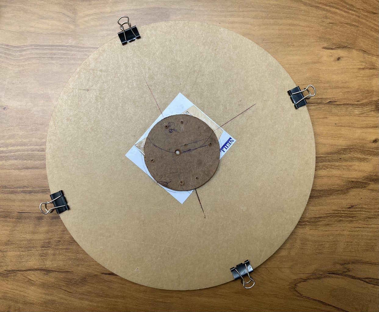
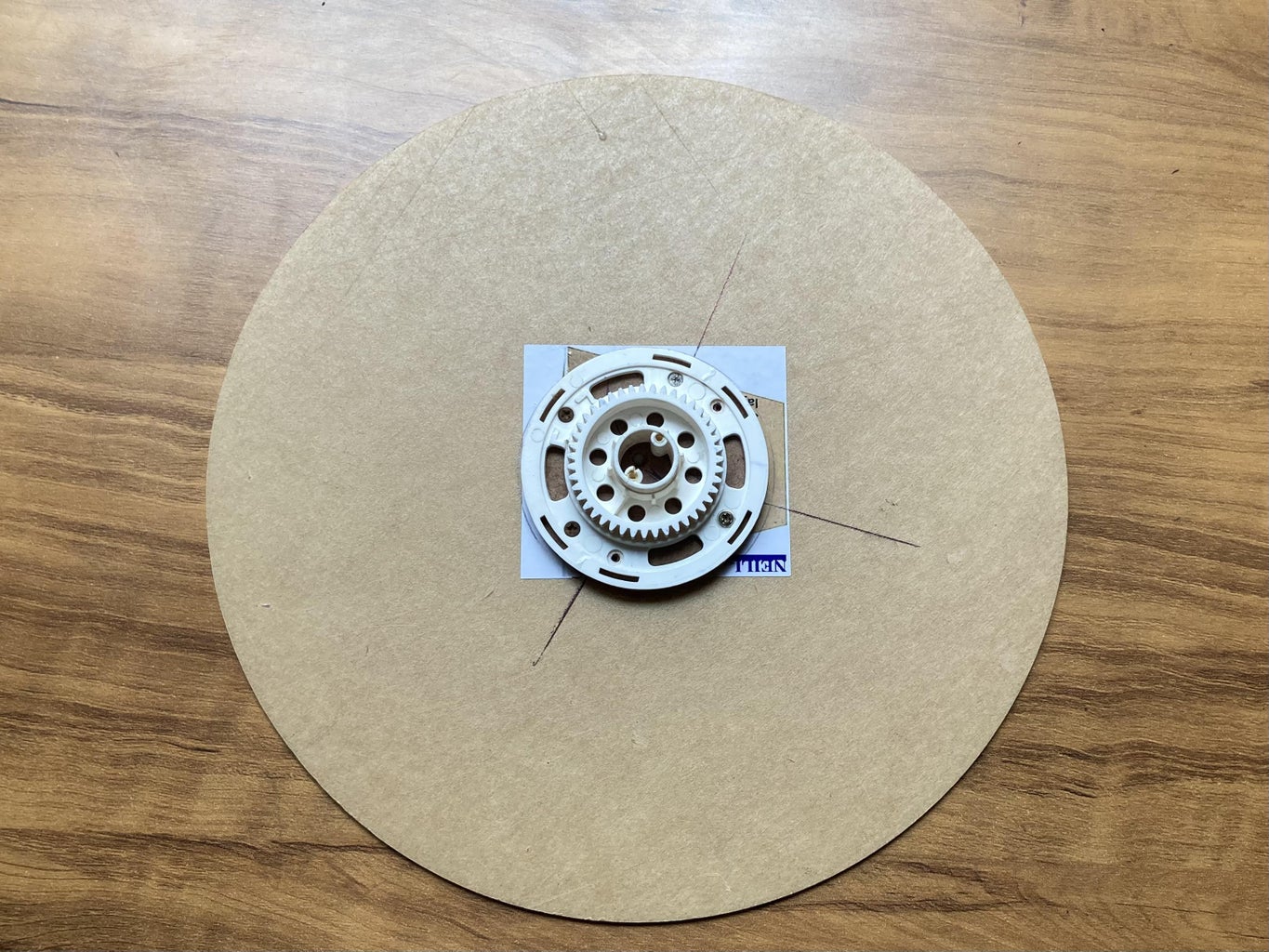
A circular piece of cardboard sheet is attached to the back of circular Acrylic sheet of (size 20 cm dia.).
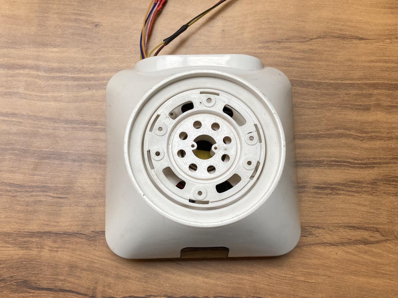
This circular acrylic sheet is fitted on the top of driven gear with the help of screws.
The driven gear is supported by a bearing already fixed in the Wi-Fi camera body.
The Arduino Uno with ULN2003 motor driver as per the circuit diagram enclosed in the body of Wi-Fi camera.
A separate power port is used to power up the ULN2003 motor drivers along with stepper motors, Servo motor and LED light Strip.
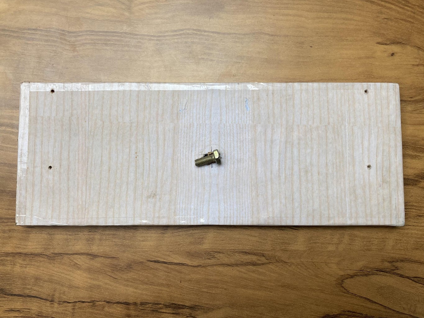
The body is now attached to the wooden piece with the help of a screw.
The wooden piece (29cm X 10cm X 1.2cm) is covered with a Wood texture colored paper or you can use paint as well.
Note: The center of rotary table should be marked on the acrylic sheet because it is essential for a polar coordinate system.
Step 3: Build Z-Axis (Pen Holder)
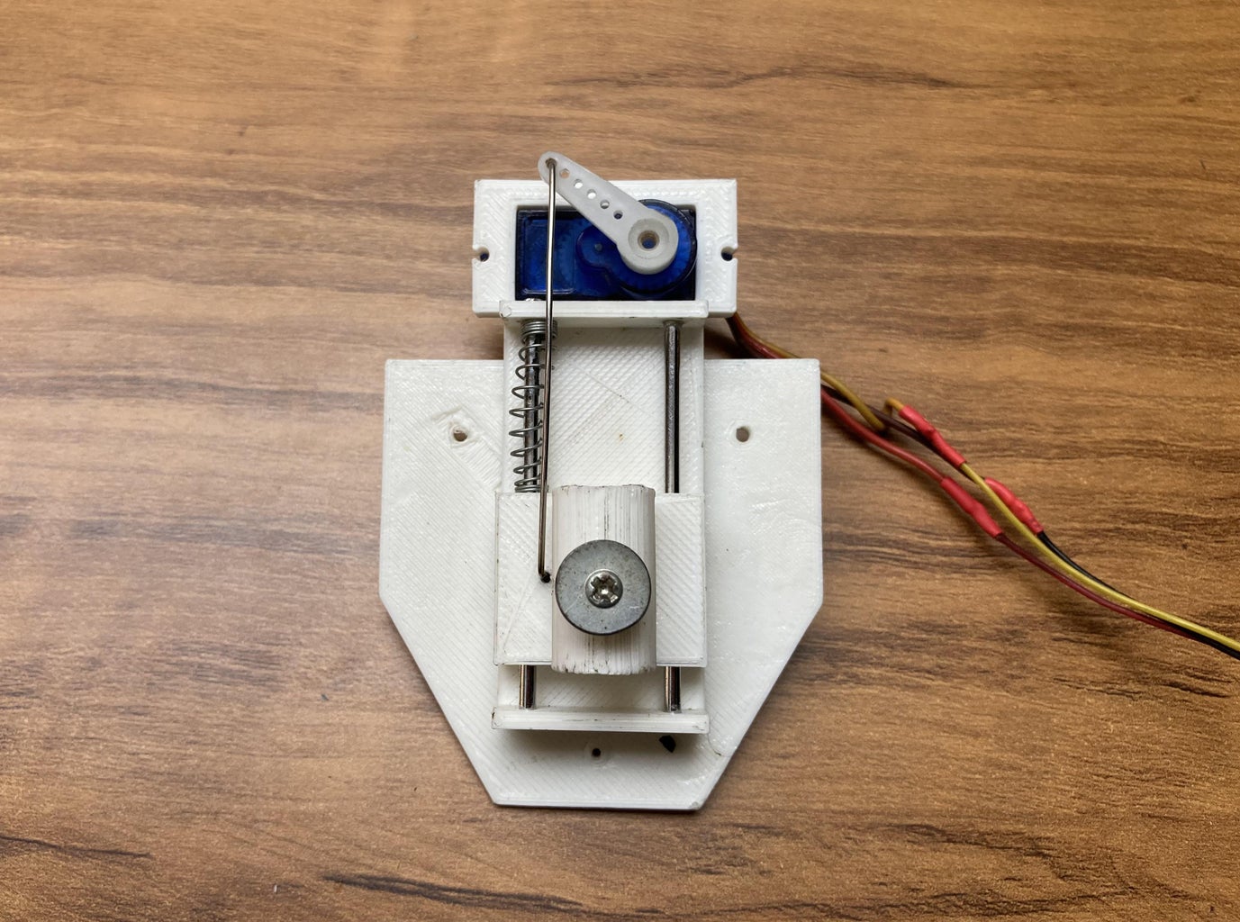
Z-axis consists of a servo motor and a pen lifting mechanism which consists of a 3D printed slider on smooth steel rods (mm dia.) and a pen spring.
A separate 3D printed part is used to hold servo motor. The whole assembly of the Z-axis i.e. servo motor is attached with the parts of X-axis with the help of superglue.
A wire is attached is to the rotary axis of the servo motor and the pen lifting part so that the pen tip can lift move up and down.
Step 4: Schematics and Circuit Diagram
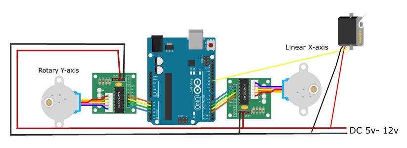
The Polar CNC Plotter general parts includes two 28BYJ-48 stepper motors and a servo motor controlled by Arduino Uno with the help of two ULN2003 stepper motor drivers. It consists of Y axis as a rotary table, X axis move linearly forward and backward relative to the center of rotary table and Z axis (servo motor) move linearly up and down to carry out lift a pen up/down.
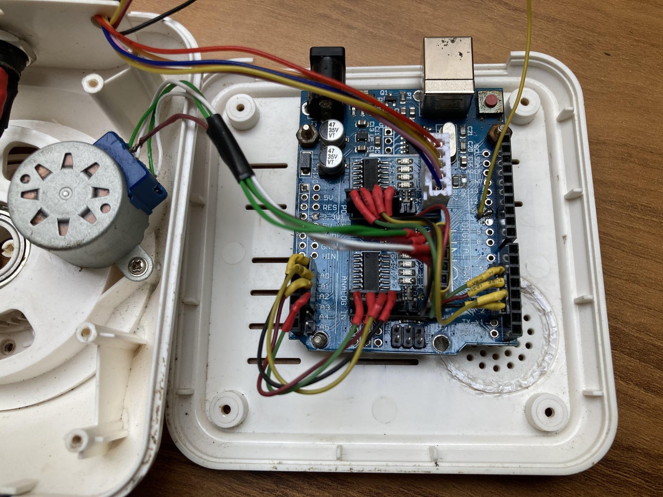
The motors (28byj-48) are connected to a controller card (Arduino UNO) that uses the chip ULN2003.
This board is connected to pins A0, A1, A2, A3 for the Y-Axis (IN4->IN1)
2,3,4,5 Digital pins to the X-Axis (IN4->IN1).
The servomotor connected to pin 11 of Arduino UNO
All the components is powered with an external power supply (5v -12v DC).
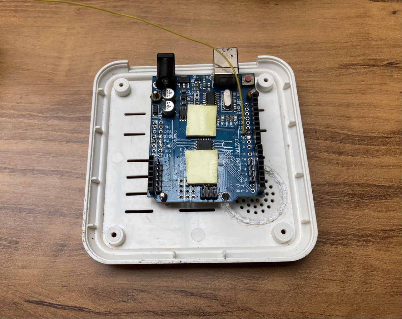
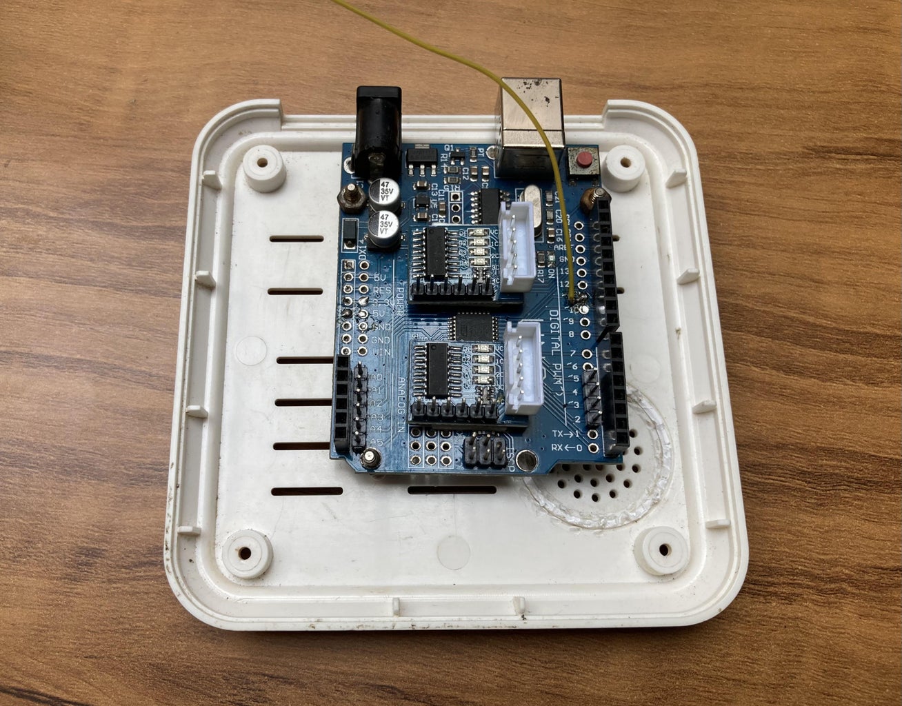
Step 5: Assembling All Parts

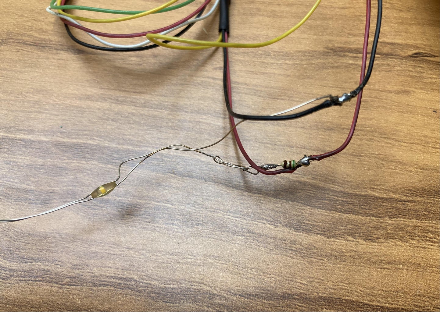
Assembling all parts together. Make proper connections of stepper motors, ULN 2003 stepper drivers and servo motor with the Arduino UNO as per the circuit diagram.
Place the ULN 2003 stepper drivers on the Arduino Uno with the help of double sided foam tape.
Use jumper wires to make necessary connections as per the circuit diagram.
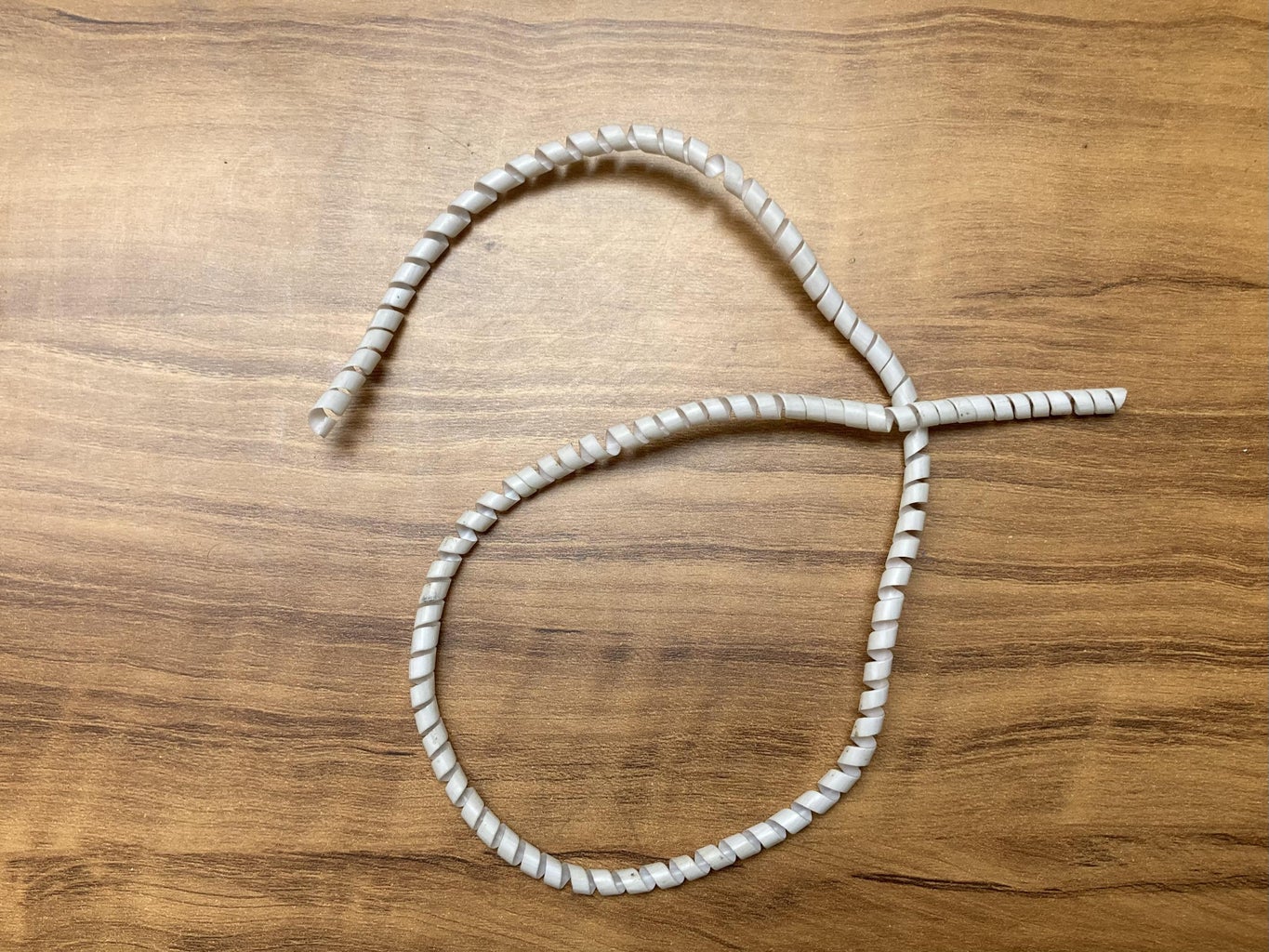
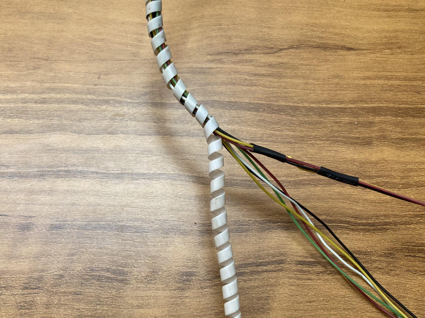
Wrap up the wires of all X-axis stepper and servo motor together with the help of a plastic straw. I converted a plastic straw into a spiral cable wrap/ cable sleeve with the help of a pencil sharpener.
Hold this cable sleeve with one of the 3D printed vertical stands with the of zip ties. Make sure that the hanging cable sleeve does not touch the rotary table.
Adjust the X axis and Z-axis (pen holder) so that the pen tip should coincide with the center of rotary table.
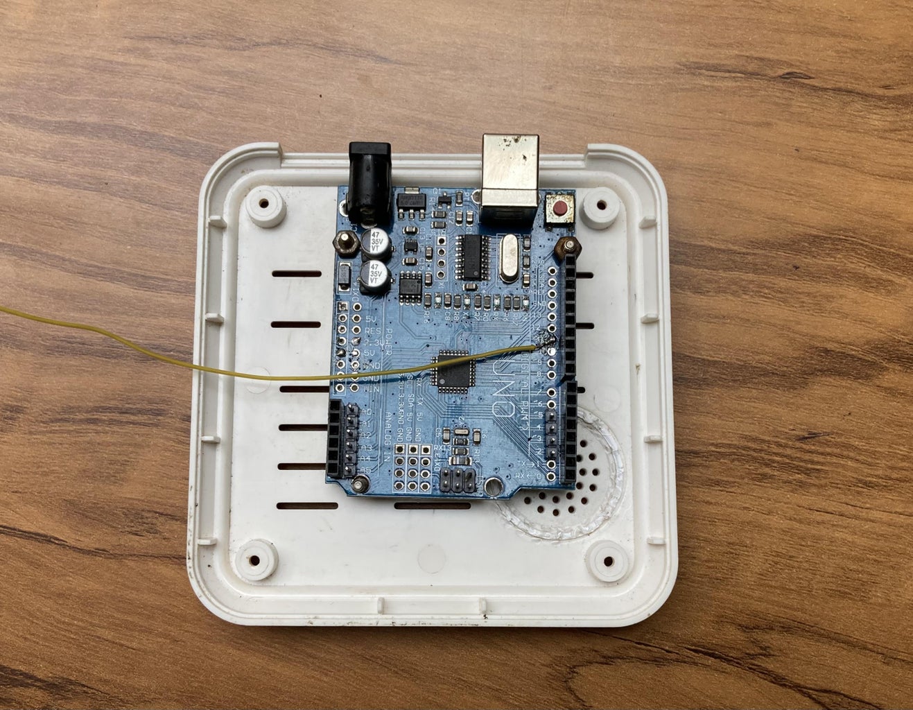
Mount Arduino Uno along with ULN 2003 Stepper motor drivers inside the body of wifi camera properly.
Close the body of the camera with the help of screws.
The Assembly of all parts is done.
Step 6: GRBL Firmware
Download and install GRBL firmware for Arduino Uno:
https://github.com/ruizivo/GRBL-28byj-48-Servo
This GRBL uses an ugly hack to control two motors unipolar stepper motors as 28byj-48 and also supports a servo motor on pin 11.
GRBL Settings:
X axis travel resolution ($100) : It is calculated on the stepper motor’s step angle - steps per revolution
Y axis travel resolution ($101): The Y axis rotates, so we have to calculate it. Steps/mm of rotary Y axis is defined by angle in polar coordinates i.e. steps/degree (STEP/° ):
Stepper motor step angle: According to the data sheet, when the 28BYJ-48 motor is operated in full-step mode, each step corresponds to a rotation of 11.25°. This means there are 32 steps per revolution (360°/11.25° = 32).
In addition, the gearbox inside the motor has a 64:1 gear reduction. This results in 2048 (32*64) steps per revolution.
My Plotter’s Gear ratio= 12:43
Y axis STEP/mm ($101) = STEP/ANGLE = (2048 x 43)/ (360° x 12) = 20.38 STEP/°
NOTE: This value does not work for my machine. So, I put different values for STEP/°in the UGS by sending command in UGS to move 360mm. After several attempts the Rotary Y-axis rotated exactly one revolution. The value of STEP/° for my plotter is 16.233
STEP/° is the key for the CNC machine to work properly in polar coordinates based on GRBL firmware.
Step 7: Inkscape to Generate Gcode
I used Inkscape software to generate G-code.
Steps for generating Gcode in Inkscape:
Download older version of Inkscape i.e. Inkscape 0.48.5 and download MakerBot UnicornGcode extension from the following links:
https://inkscape.org/release/inkscape-0.48/?latest=1
https://github.com/martymcguire/inkscape-unicorn
MakerBot Unicorn Gcode extension helps in creating the G-code files from texts or images.
After downloading MakerBot Unicorn Gcode extension, copy the files of this extension and paste these files inside the extensions folder of Inkscape.
In my computer system the location of Extensions Folder as shown below:
C:\Program Files\Inkscape\share\extensions
Open INKSCAPE.
Click on File tab > Document properties > Width and Height to 100mm each.
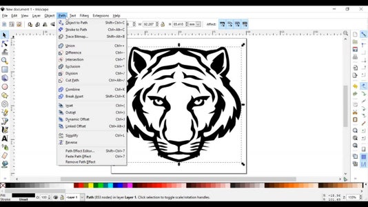
Drag and drop the particular image in Inkscape > Select Image > Convert to Path > Delete the original image > Path tab> Object to path
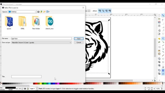
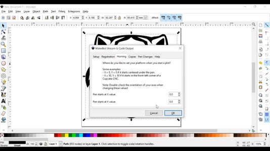
Go to File tab > Click on Save As > file name. MakerBot Unicorn Gcode extension , adjust the values on the pop-up box. My setting is shown in the picture below:
NOTE: The Homing value of X and Y should be 0.0
After generating Gcode, open Gcode file in notepad and do the following changes to gcode:
Replace M300 S30.00 (pen down) with Z-1
Replace M300 S50.00 (pen up) with Z0
Also remove upper and lower part of Gcode
You can take the help of this video to generate Gcode from Inkscape.
After making these changes, save the file.
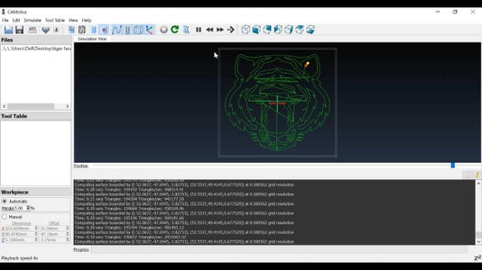
You can simulate this gcode using CAMotics software which is a open-source simulation software.
CAMotics downloading link:https://camotics.org/download.html
Step 8: Cartesian to Polar Conversion Using TkCNC Editor 3.0
tkCNC Editor 3.0 is a text editor, specially designed for CNC code (G-code) editing for CNC machines. It is used by CNC programmers and operators for fast editing and verification of CNC code. It is available for download with 30 days trial version. I used this software for Conversion of G-code from Cartesian to Polar coordinates.
You can download and install tkCNC Editor 3.0 from the following link:
https://www.tkcnc.com/download.html
Steps to convert Cartesian gcode to Polar gcode using tkCNC Editor 3.0:
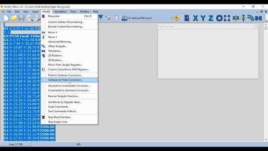
Open tkCNC Editor 3.0
Go to File tab > Open CNC file
Select the whole gcode with key combinations Ctrl+A
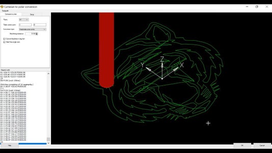
Go to "Modify" > Click on Cartesian to Polar Conversion, a polar coordinate settings window pops up.
Plane: XY.
Conversion type: Interpolate polar points.
Machining tolerance = 0.010.
Select both tick boxes: Start from angle zero and Infinite rotation axis.
Click "OK" and then conversion is started.
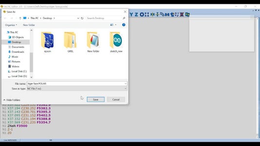
After Cartesian to Polar Conversion save the file with “.nc ” extension.
Open the file in notepad and do the following changes in Gcode:
Replace All Z-1 with M3 S30
Replace All Z0 with M5
Replace All ZNaN F3500 with Blank Space
Replace All N1 with Blank Space
Replace All C with Y
NOTE: The servo motor understands the commands M5 and M3 S30 which corresponds to Pen Up and Pen Down respectively. Polar coordinates are represented by X and C in this software. We need to replace "C" by "Y" so that the GRBL firmware can understand these commands.
Now save the file with a different name.
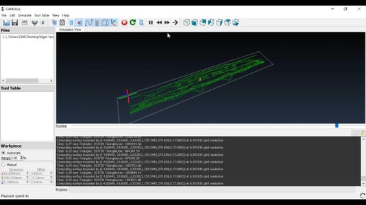
You can test/simulate this polar Gcode with CAMotics Simulation Software. You find that this Gcode works properly. Hence we successfully converted a Cartesian Gcode to Polar Gcode.
See the video for more help.
As we already uploaded the GRBL firmware to the Arduino Uno so we are ready to test this polar Gcode on Polar CNC Plotter.
For this we need Universal Gcode Sender(UGS), it Sends the G-code file to Polar CNC plotter and monitors the CNC in action on its Visualize Window.
You can download UGS from the following link:
Step 9: Working
Connect USB Cable to Arduino Uno port and 5V DC power to the power port.
Cut a 20cm diameter circular paper sheet from a A4 white paper sheet and place this sheet on the acrylic rotary table of the Polar CNC Plotter.
Hold this paper sheet on circular acrylic sheet with the help of paper 3 paper clips.
Put color pen in the pen holder of the plotter.
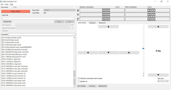
Open UGS, select Port and set Baud to 115200, click on Connect tab.
Set the original coordinates by button Reset Zero. It should be located in the center of rotary axis.
Click Open > Browse to the G-code file "tiger face POLAR.nc" that is converted by tkCNC Editor.
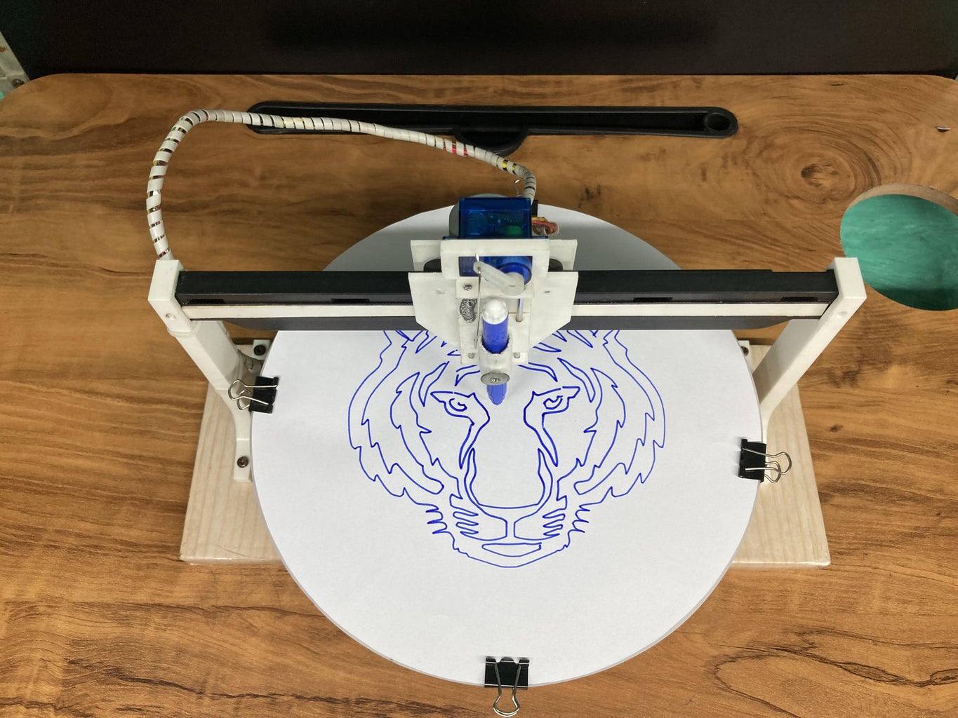
Click Send buttonand Polar CNC Plotter will start drawing the image.
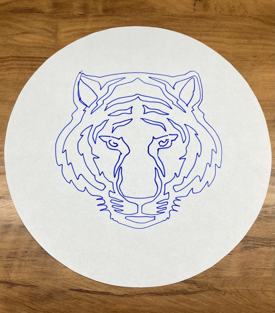
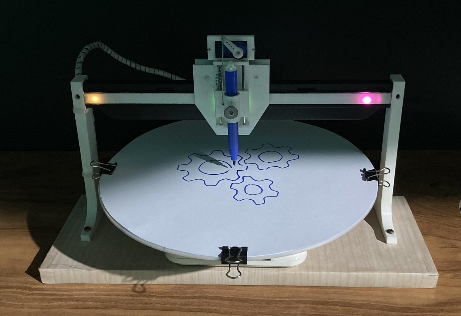
The image below shows a tiger face drawn by a Polar CNC machine afterconversion of Cartesian to Polar coordinates. I also tested the Polar CNC machine by drawing three gears.
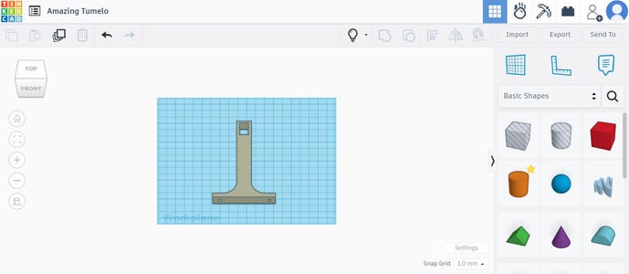
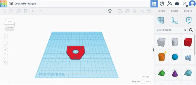
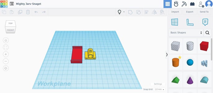
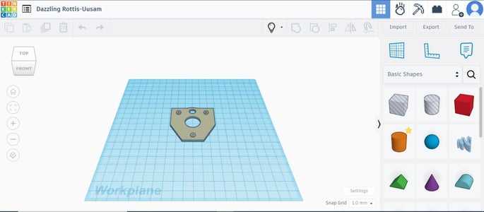
Step 10: STL Files


Step 11: Final Words
I made this project from old scrap materials such as old wifi camera, old LaserJet printer, discarded tape recorders, and some 3D printed parts to make a low cost Polar CNC Plotter.
If you have any query regarding this tutorial, feel free to ask in comments section.
Hope you enjoyed this session of Instructables. Thanks for reading my work. I feel glad if you make your own Polar CNC Plotter with the help of this tutorial.
Stayed tuned to my Instructables channel for more upcoming exciting projects.
Thanks again.

This is an entry in the
Anything Goes Contest