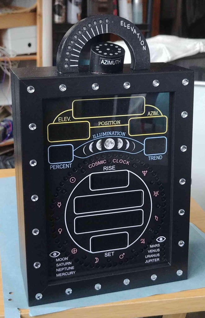
Introduction: Planet Locating 'Cosmic Clock'
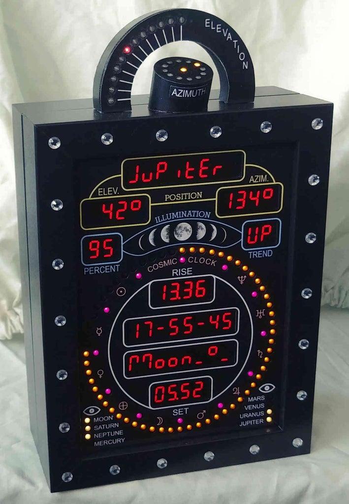
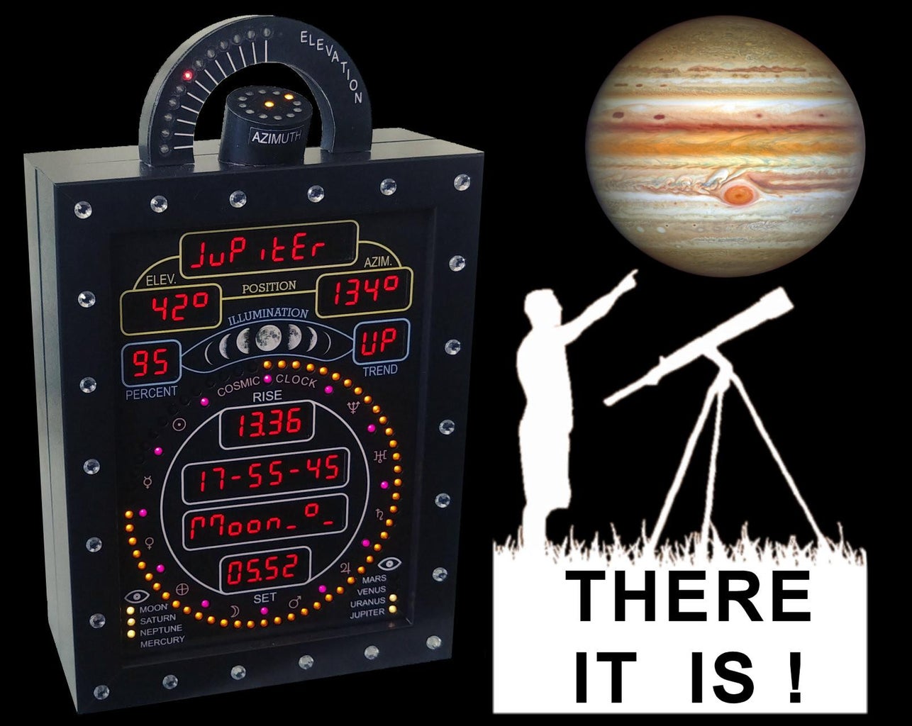
Another clock I hear you say. Well, I'd like to think that this one is a little unique. Called the 'Cosmic Clock', it combines cost effectiveness, high presentation levels, a large degree of configurability, and provides major solar system objects visibility information. It has been designed to be relatively straightforward to build, albeit rather labour-intensive, with a minimal set of associated tools needed to help in its construction.
The Cosmic Clock has the following features:
- A real time clock (using a DS3231 with battery backup), with 12 different time display modes.
- Seconds that are simultaneously displayed on an outer 60 yellow LED ring, with up to 18 possible animation modes that can be selected or not to automatically cycle every 10 minutes through your 6 favourite ones.
- A ring of 12 pink LEDs (adjacent to the 60 yellow LED ring) that provide visual indicators for every 5 seconds of time, with 11 possible animation modes that can be selected or not to automatically cycle every 15 minutes through your favourite ones.
- A display brightness that is automatically adjusted according to the ambient lighting conditions.
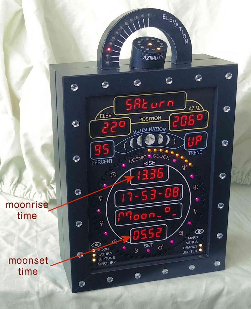
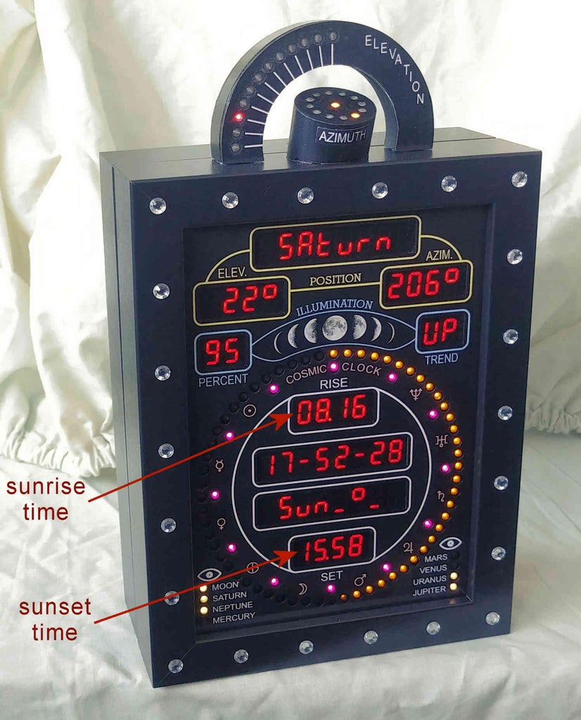
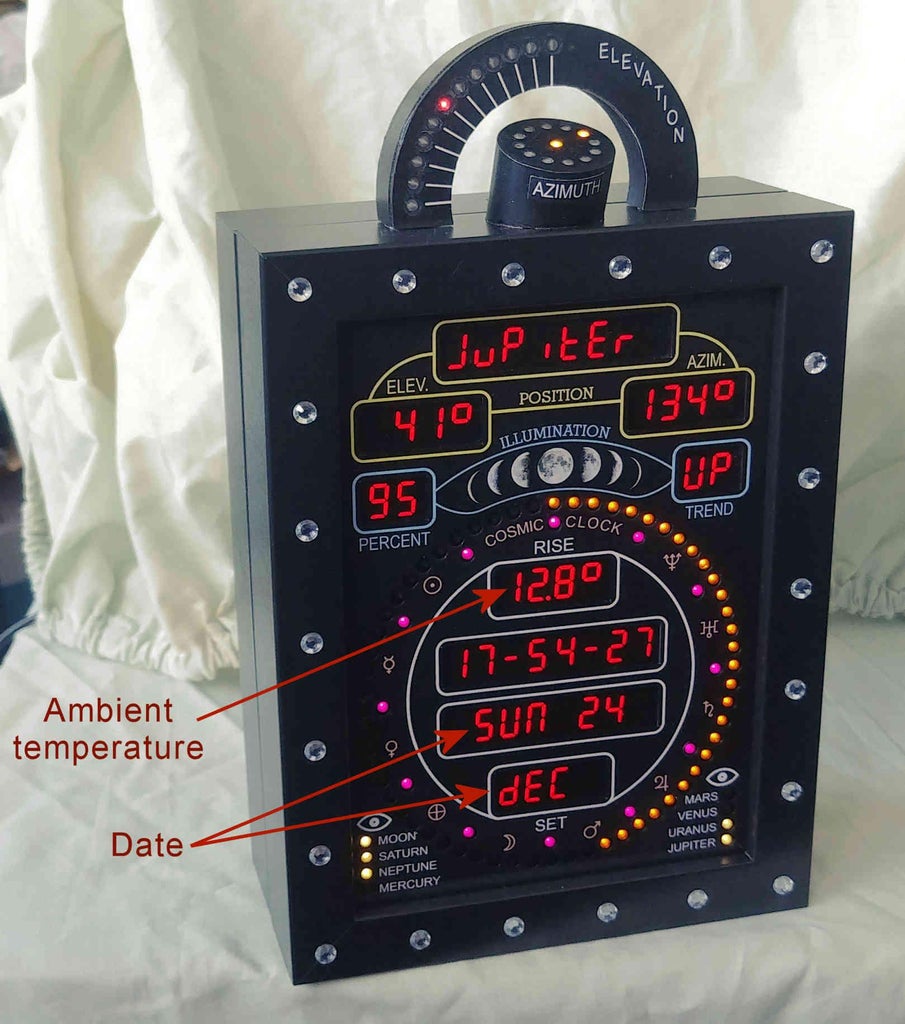
- Displays the current date and temperature, together with Sun and Moon rise/set times.
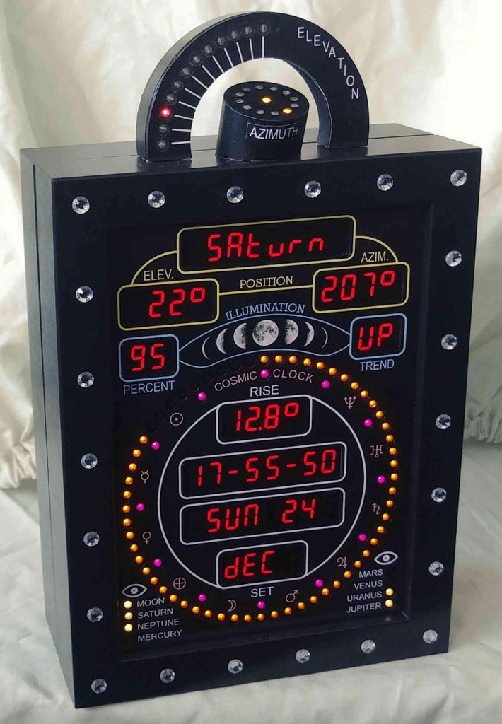
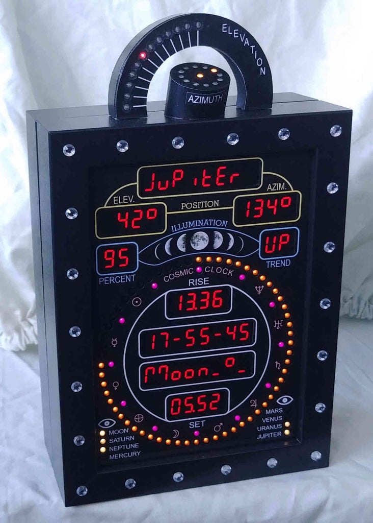
- Displays, in a cyclical fashion (on 7-segment displays), the current elevation and azimuth angles of all the planets and the Sun and Moon. All calculations are made within the ATmega644 microcontroller itself (ie, no internet access is needed).
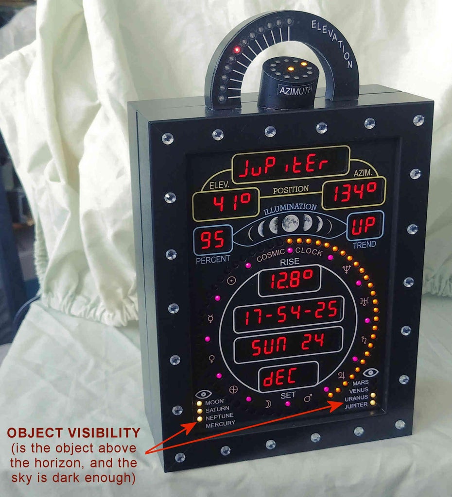
- Displays via lit white LEDs which of the planets/moon are visible, based on whether the object is above the horizon and the sky is dark enough.
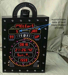
- Displays the approximate date of the next major meteor shower.
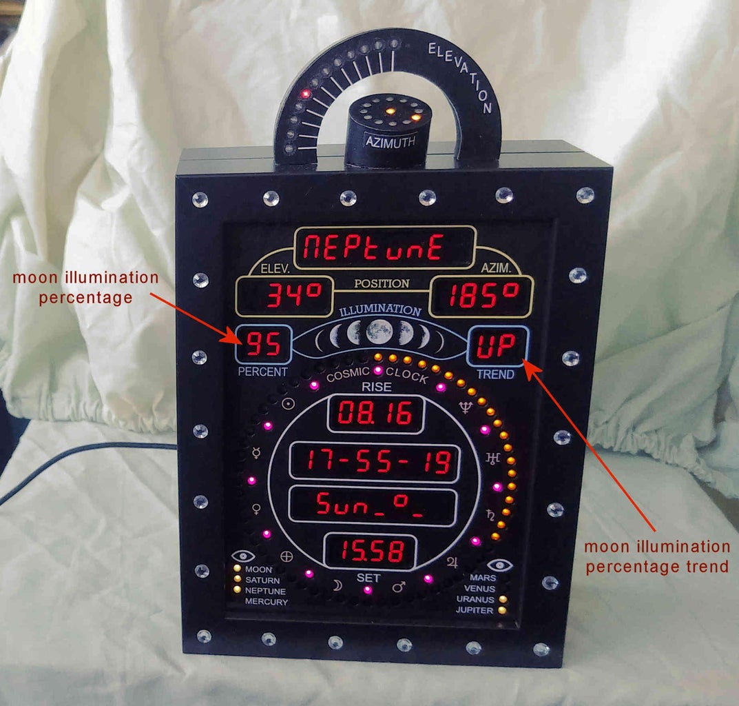
- Displays the Moon's illumination percentage and Moon's illumination trend (increasing or decreasing).
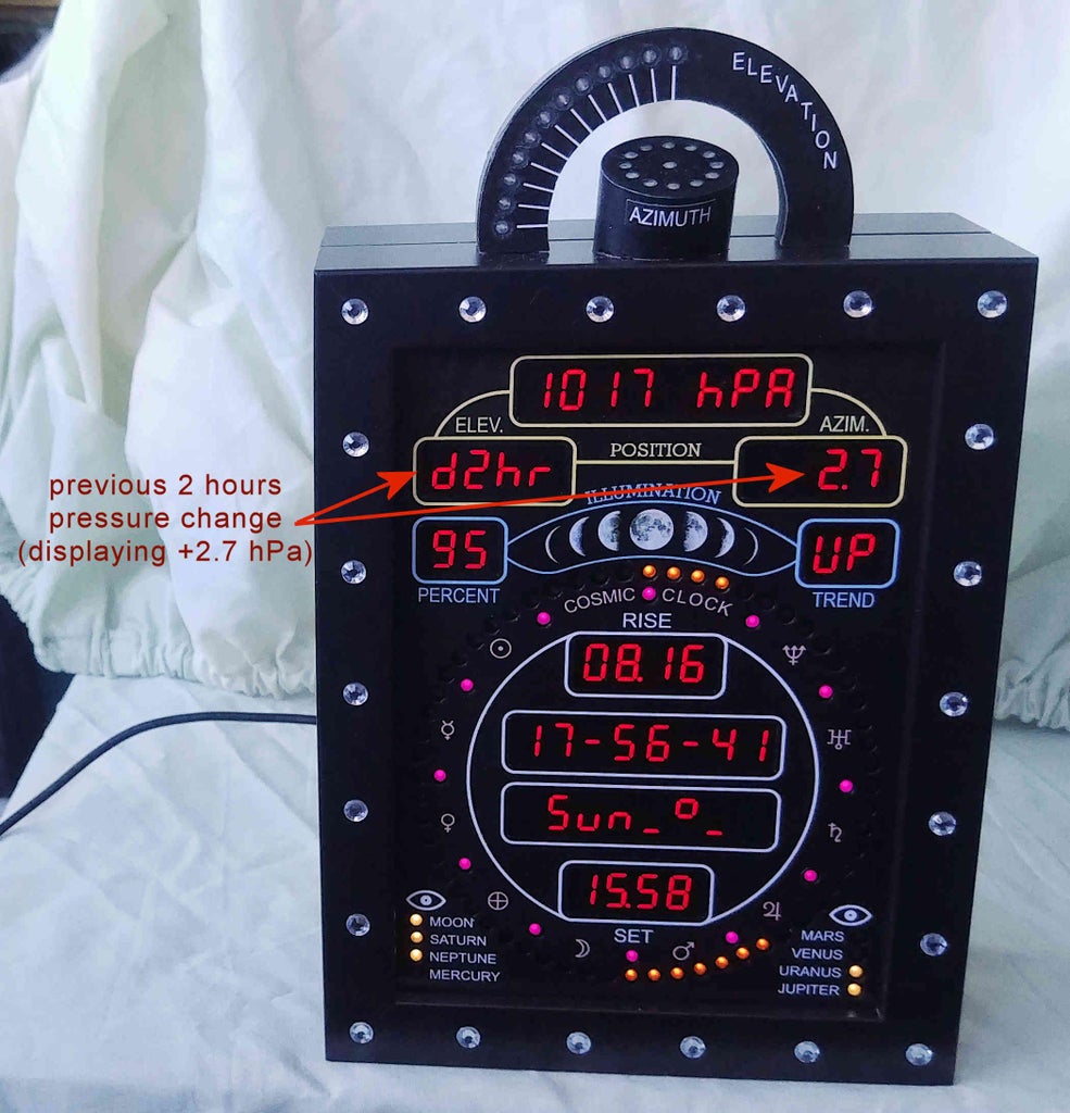
- Optionally displays the current pressure, and the pressure trend over the previous 2 and 4 hours (if a BMP180 pressure sensor is fitted).
- Optionally, using an arc of 12 LEDs, and a separate circle of 12 LEDs to indicate the elevation angle and the azimuth angle respectively, it literally 'points' to the position in the sky of the planets and the Sun and Moon.
Supplies
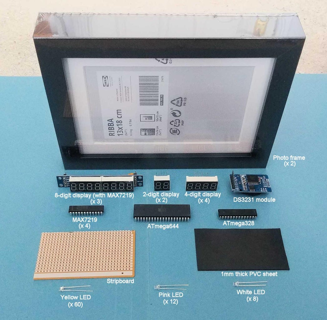
Required parts
- IKEA RIBBA 13cm x 18cm photo frame (CODE : 503.784.48) x2
- 1mm thick black PVC sheet of size at least 15cm x 45cm
- 2mm thick hardboard of size at least 210mm x 160mm
- 8-digit, 7-segment display with integrated MAX7219 (0.36" digit height) x3
- 4-digit, 7-segment displays (0.36" digit height) x4
- 2-digit, 7-segment displays (0.36" digit height) x2
- 3mm yellow LED x60
- 3mm pink LED x12
- 3mm white LED x8
- 1 sheet of A4 sized 90-100gsm white paper
- 1 sheet of A4 sized printable transparency sheet
- 1 piece of stripboard (veroboard)
- ATmega644 or Atmega1284 DIL package microcontroller
- ATmega328 DIL package microcontroller
- MAX7219 DIL package display driver x4
- Various electronic sundries, eg, resistors/capacitors/switches/power connector (see circuit schematic for details)
- DS18B20 temperature sensor
- DS3231 clock module
- Sheet of relatively heavily tinted grey or brown transparent material of thickness approx 0.1 to 0.2mm
- PVC adhesive
- Tube of Dowsil 732 multi-purpose silicone sealant (or similar)
- M2 x 20mm long countersunk screw x12
- M2 nut x36
- M2 washer x36
- Power supply (7.2V DC or 9V DC) with at least 1A current rating
- M3 x 16mm countersunk screw x8
- No.4 x 3/8" self tapping screw x24
- M3 washer x40
Optional parts
- Arduino Uno to program ATmega644 and ATmega328
- BMP180 pressure sensor (to optionally display pressure information)
- Voltage level shifter board for BMP180 (to optionally display pressure information)
- 2-part epoxy adhesive
- 209 grey acetate sheet A4 size (0.3 ND)
- Section of PVC rod of diameter at least 83mm (to make optional top frame mounted elevation and azimuth pointing indicators)
- Additional 3mm red LED (for top frame mounted elevation indicator) x12
- Additional 3mm yellow LED (for top frame mounted azimuth indicator) x13
- Adhesive gems of size 3mm to 6mm for aesthetic purposes to enhance the photo frame
Tools
- Saw
- Rotary tool, eg. Dremel (optional)
- Drill (A pillar drill or bench drill is best) and M3 drill bit
- Set of needle files
- Scalpel knife
- Screwdriver
- Soldering tools and supplies
- Ruler
- Wire cutters
- Wire stripper
- M3 x 0.5mm hand tap
- Small countersink drill bit
- Mini pin vice
- Scissors
- 300-400 Grit sanding sheet
- Lathe, to help create the PVC pieces for the optional elevation and azimuth pointing indicators
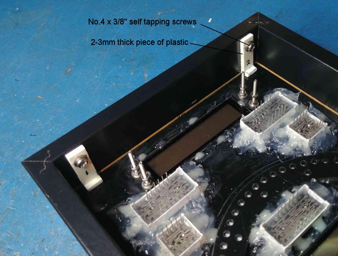
Step 1: Joining the Two Photo Frames Together
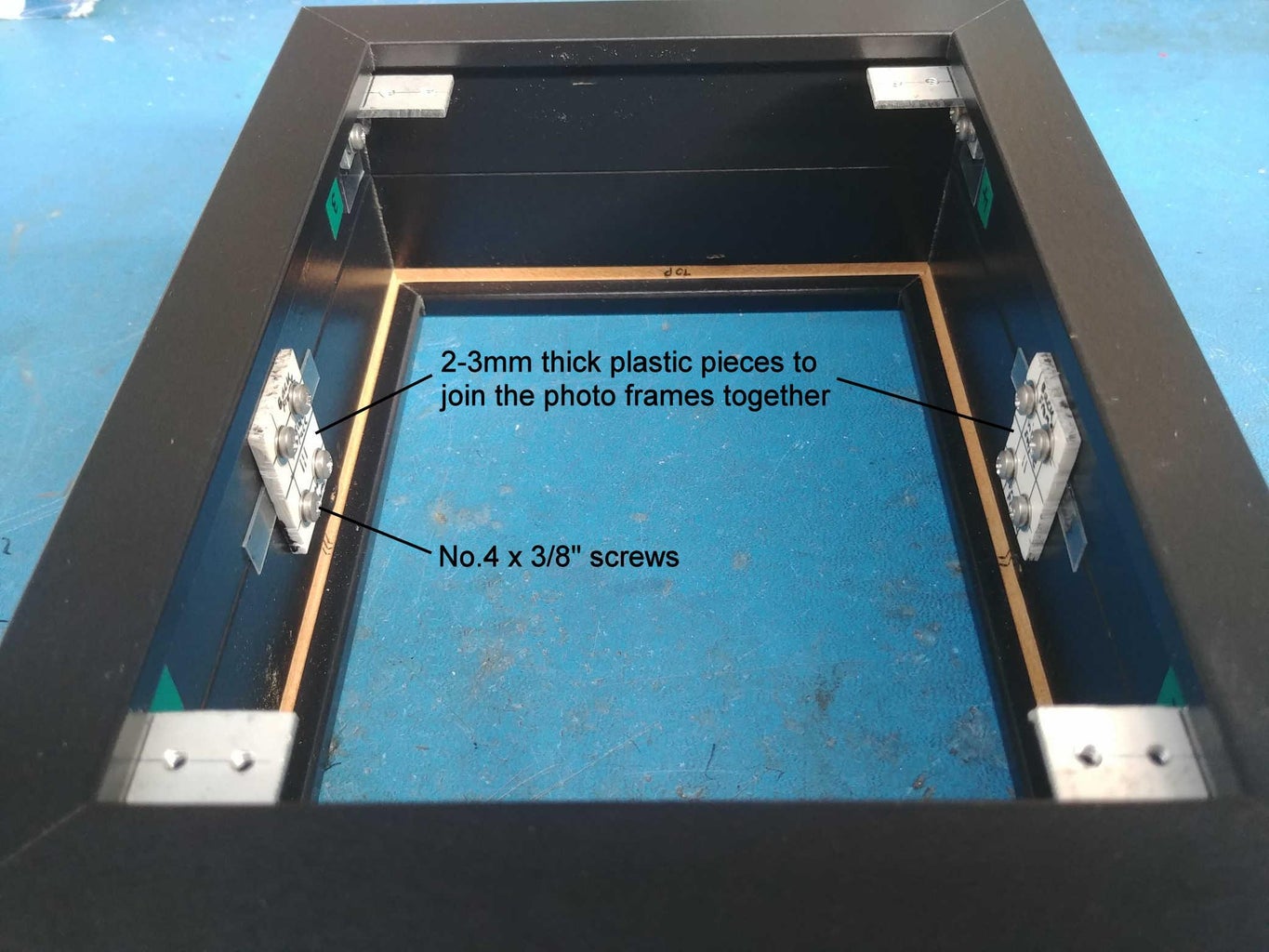
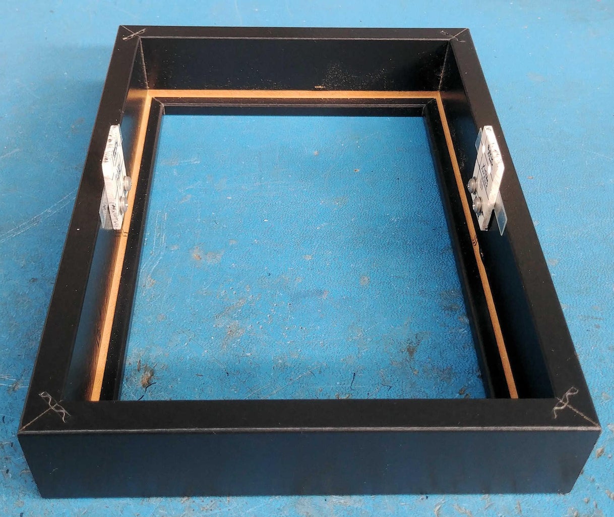
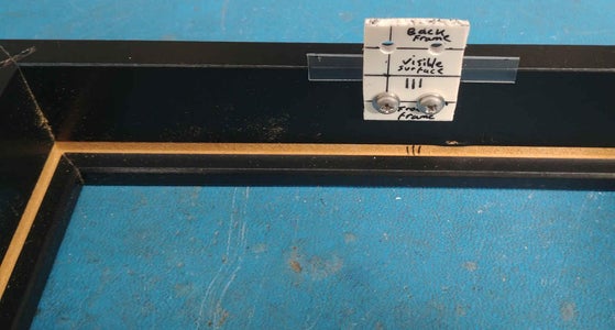
It was determined that the combined depth of two joined photo frames will give enough physical space to contain both the electronics and the front displays. So, join the two IKEA RIBBA 13cm x 18cm photo frames (CODE: 503.784.48) together using two small pieces of 2-3mm thick plastic, together with No.4 x 3/8" self tapping screws, as shown in the photo. It is highly advisable before fitting the self tapping screws to use a mini pin vise to drill 2mm diameter, 7mm deep pilot holes from the inside of the photo frame. This will minimise any chances of the frame splitting when the screws are inserted. Be very careful that this 2mm diameter pilot hole does not penetrate the outer frame surface.
Step 2: Creating a Back Cover
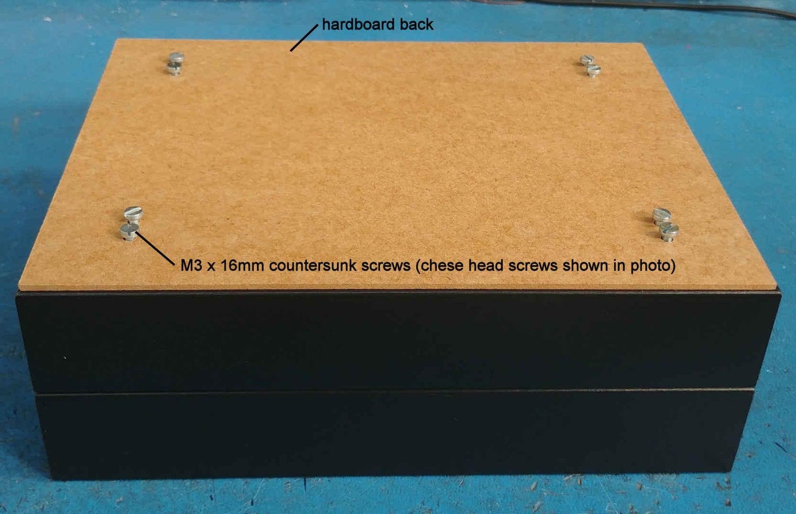
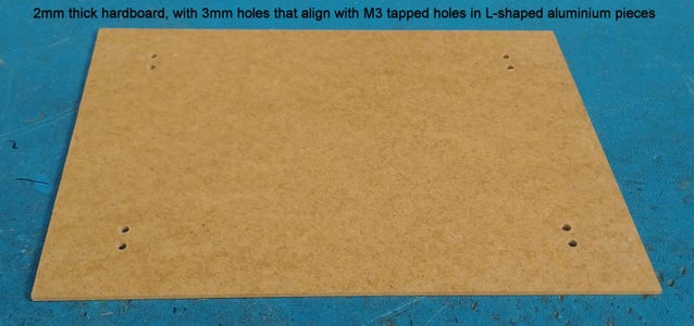
Cut a piece of 2mm thick hardboard to a size approximately 1mm less than the outer dimensions (in both width and height) of the joined photo frames (approx size 204mm x 154mm). This will become the back cover of the Cosmic Clock. Mount the hardboard to the rear of the joined photo frames using one of two methods:
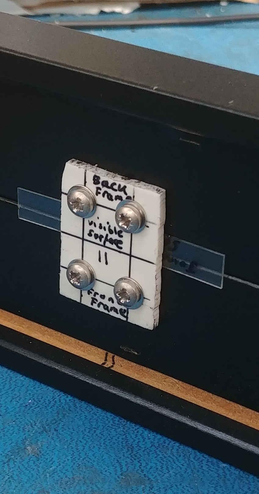
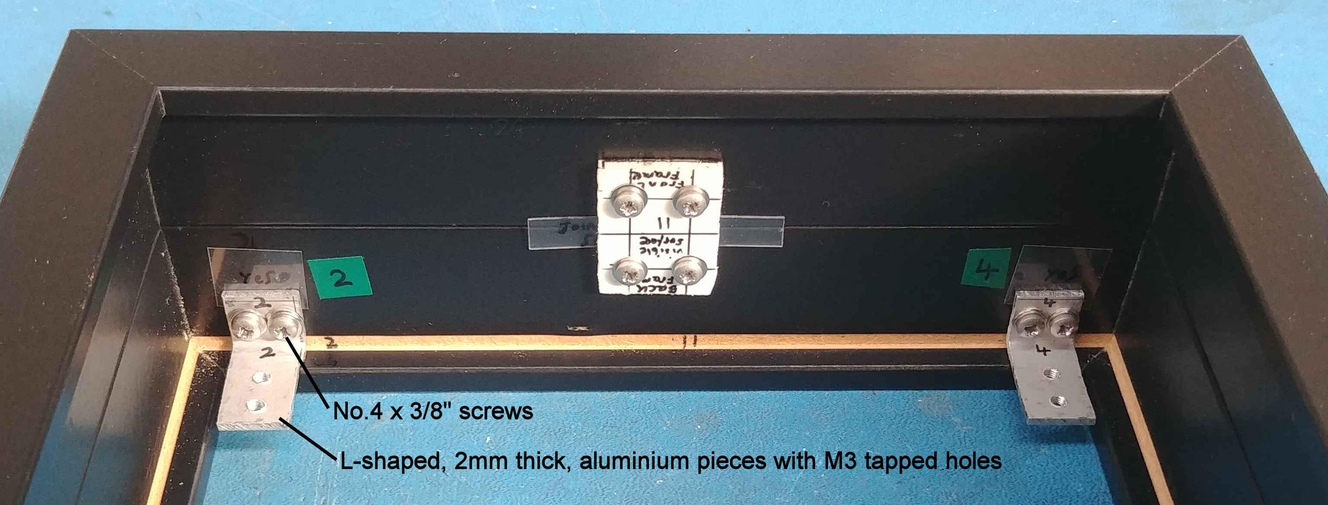
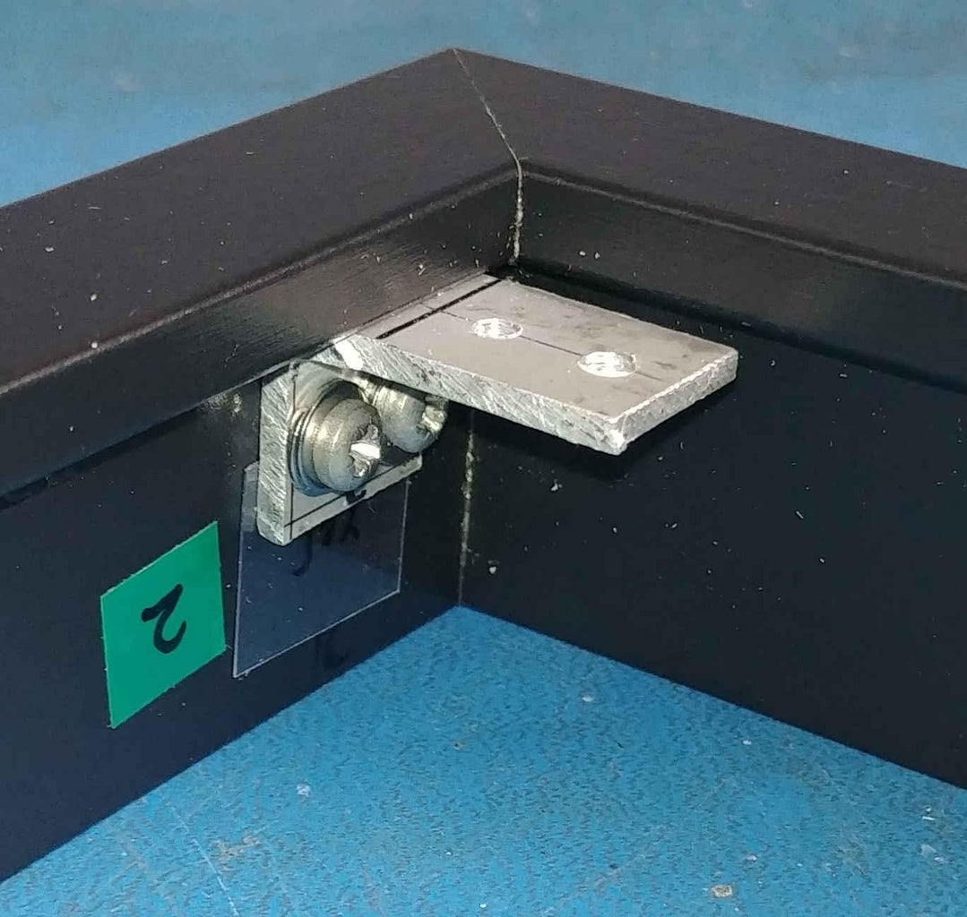
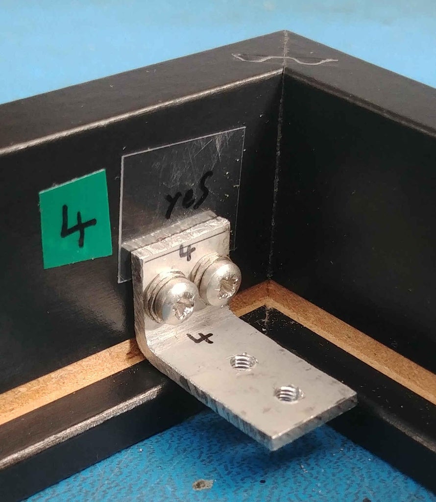
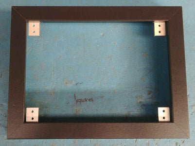
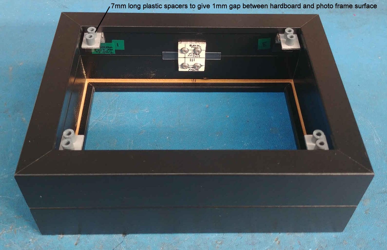
The first method, which I've shown in the photos, involves screwing four, 2mm thick L-shaped pieces of aluminium into the four corners of the rear of the joined photo frames. These L-shaped pieces have M3 x 0.5mm tapped holes in them that align with 3mm holes drilled into the corners of the hardboard. 6-7mm long plastic spacers fill the gap between the L-shaped pieces and the hardboard inner surface. It is desirable to have a small gap of about 1mm (using M3 washers acting as standoffs) between the piece of hardboard and the rear of the joined photo frames to allow for any internal warm air to vent to atmosphere. The piece of hardboard is then fixed to the L-shaped aluminium pieces (screwed to the rear of the joined photo frames) using M3 x 16mm countersunk screws.
The second method simply involves screwing the hardboard directly into the rear of the joined photo frames using No.4 x 3/8" self tapping countersunk screws. Again, it is desirable to have a small gap of about 1mm (using M3 washers acting as standoffs) between the piece of hardboard and the rear of the joined photo frames to allow for any internal warm air to vent to atmosphere.
Step 3: Cutting PVC Sheet to Create a Base for the Displays/LEDs
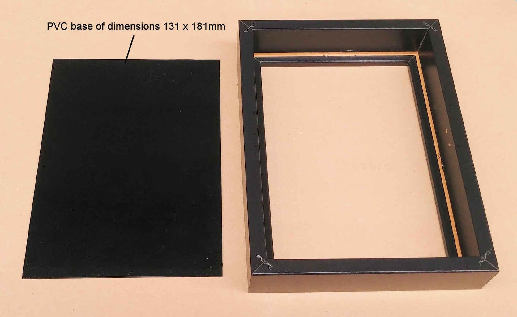
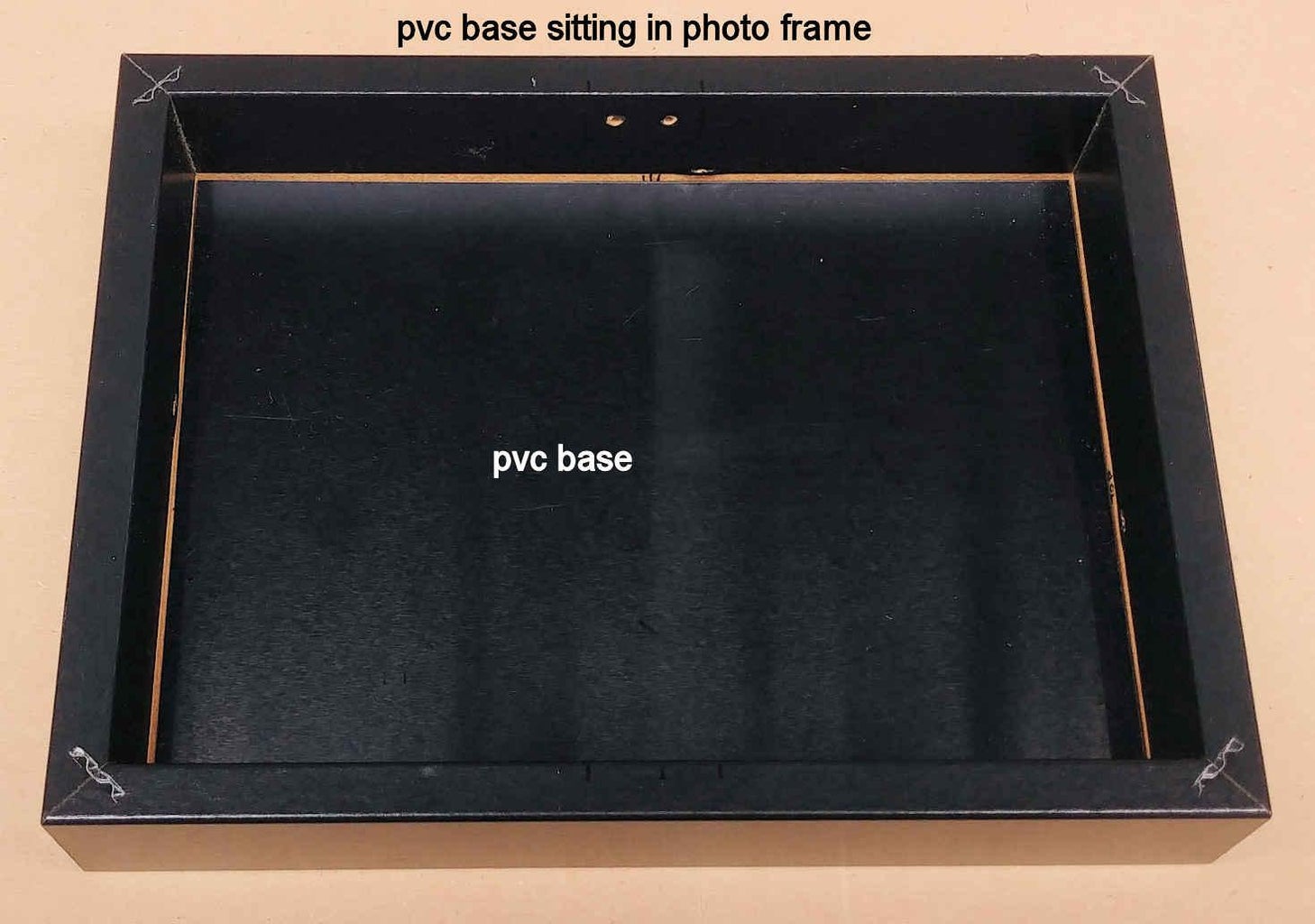
Cut from the 1mm thick PVC sheet a piece that exactly fits into the inner front of the joined photo frames (ie, in the area that the plastic transparent windows sits). The dimensions of this piece should be about 131mm x 181mm. This PVC piece, acting as a base, will have the various LEDs/displays mounted to it.
Step 4: Printing and Using the Transparency Sheet Construction Aid
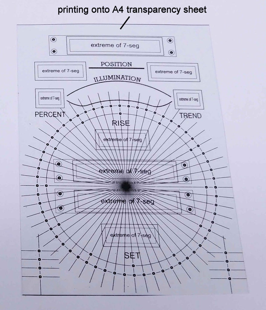
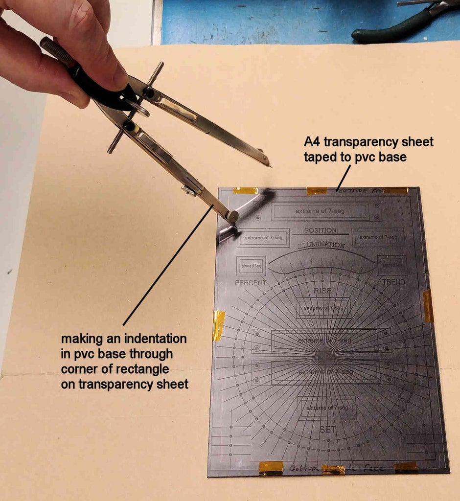
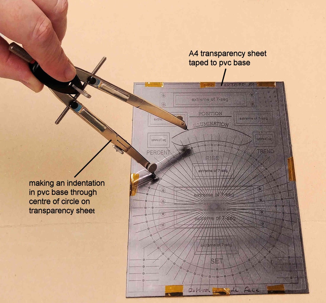
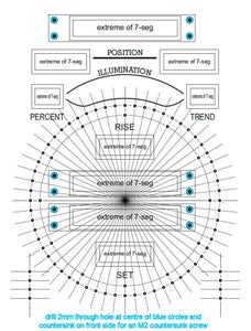
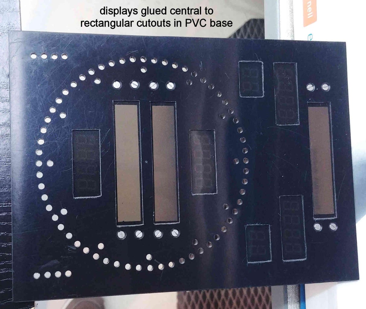
Print at 100% size (not 'fit to page') the file print_on_A4_transparency.pdf onto an A4 transparency sheet. This transparency will aid in the construction of the Cosmic Clock. Cut the A4 transparency sheet to a size a few mm smaller than the 131mm x 181mm PVC base, making sure not to cut off any of the black printed artwork on the transparency. Position the artwork on the transparency sheet exactly central on to the 131mm x 181mm PVC base, and then tape down the transparency sheet around its edges onto the PVC base to prevent it from moving.
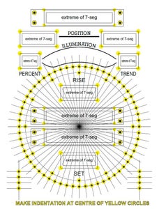
Push a sharp point (eg. the point on a compass) through the corners (highlighted with yellow circles on the attached construction photo) of the 9 rectangles on the transparency sheet so that an indentation is made in the PVC base below. Again, push a sharp point through the centre of the 92 circles (again highlighted with yellow circles on the attached construction photo) on the transparency sheet so that an indentation is made in the PVC base below.
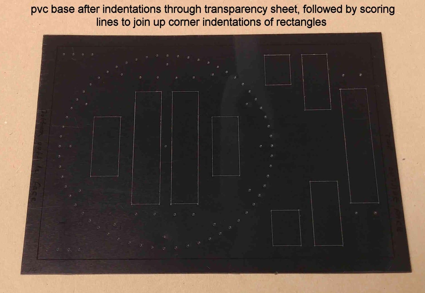
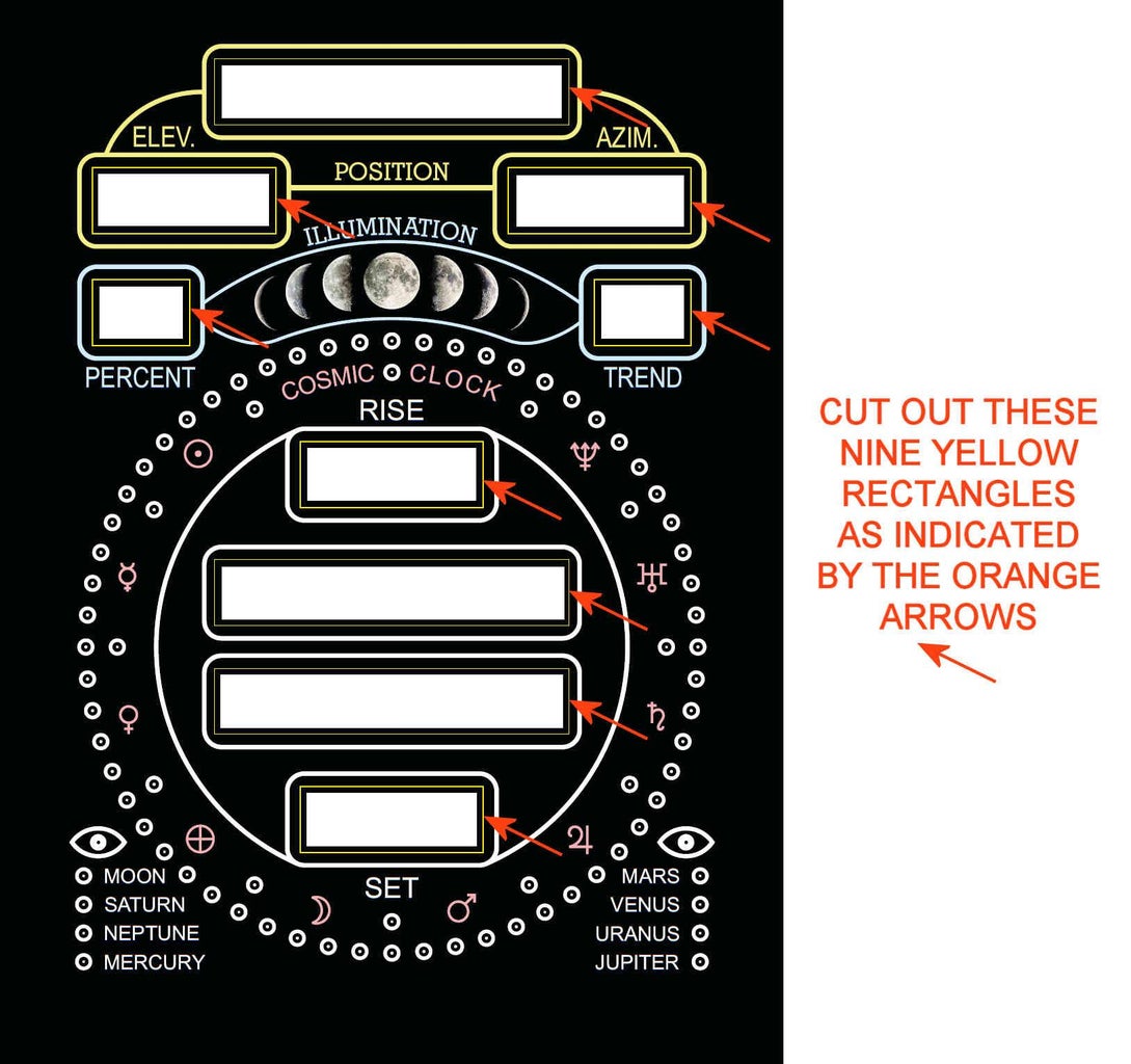
Remove the transparency sheet from the PVC base, and, with a sharp metal point, score joining lines into the PVC base to join the corners of the 9 rectangles together, thus making full rectangles that mirror the rectangles in position and size of the ones on the transparency sheet.
Attachments

Step 5: Stage 1 of PVC Base Modification
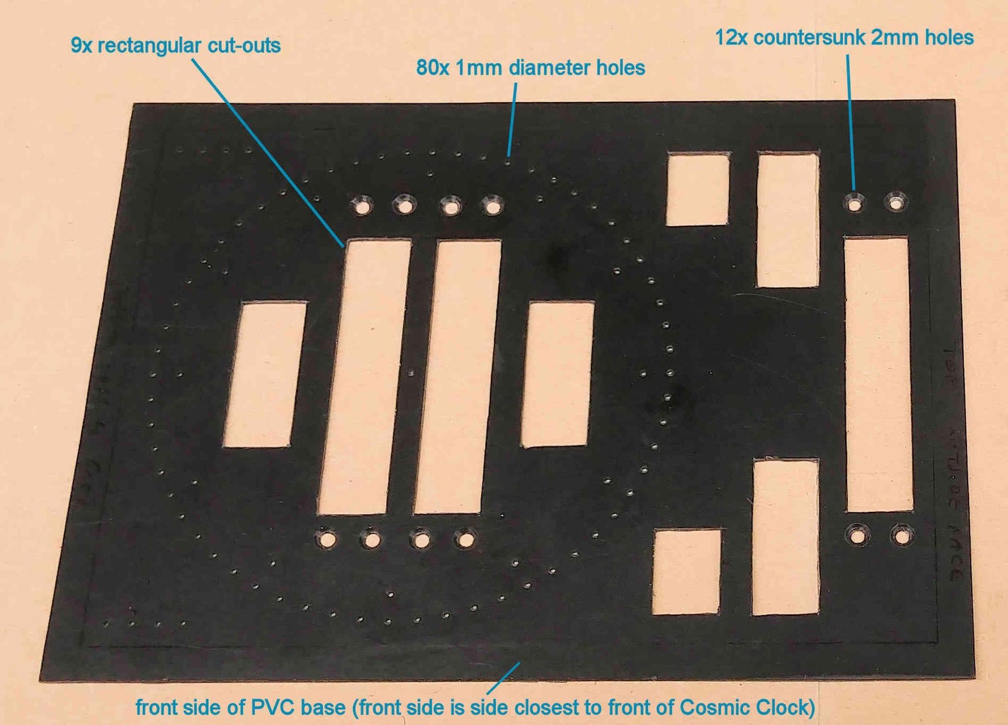
Using a combination of drills and files, cut out of the PVC base the 9 scored rectangles as generated from the previous step.
Drill twelve 2mm diameter holes at the previously indented locations (highlighted with blue circles on the attached construction photo) surrounding the 3 widest rectangles (62mm x 13mm dimensions). Countersink these twelve holes on the front side of the PVC base to accommodate M2 x 20mm long countersunk screws that will hold in place the three 8-digit, 7-segment displays. (The front side of the PVC base is the side that is closest to the front of the Cosmic Clock).
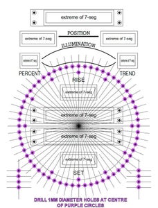
Drill 1mm diameter holes at the remaining 80 previously indented locations (highlighted with purple circles on the attached construction photo) that will eventually hold the 60 yellow, 12 pink, and 8 white LEDs.
Step 6: Stage 2 of PVC Base Modification
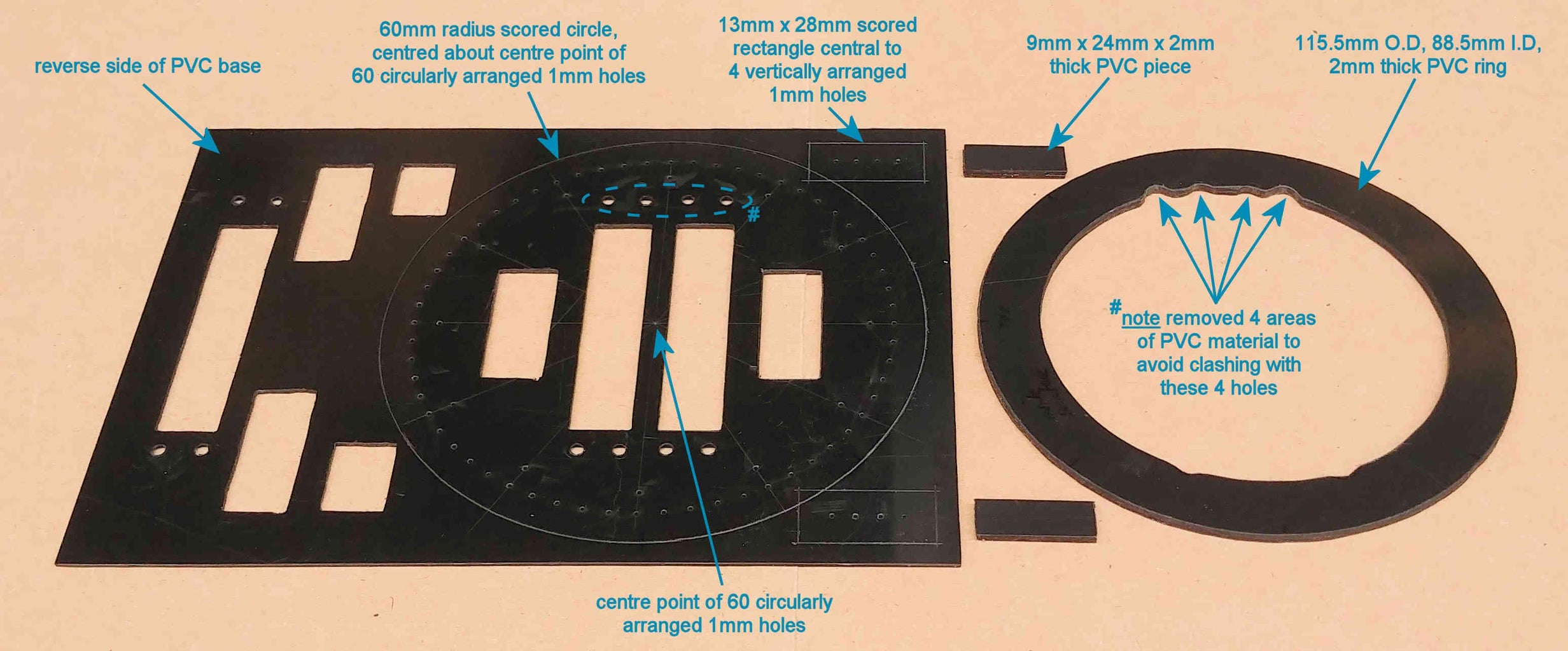
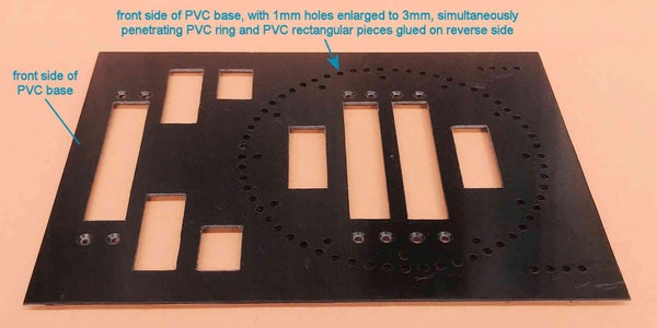
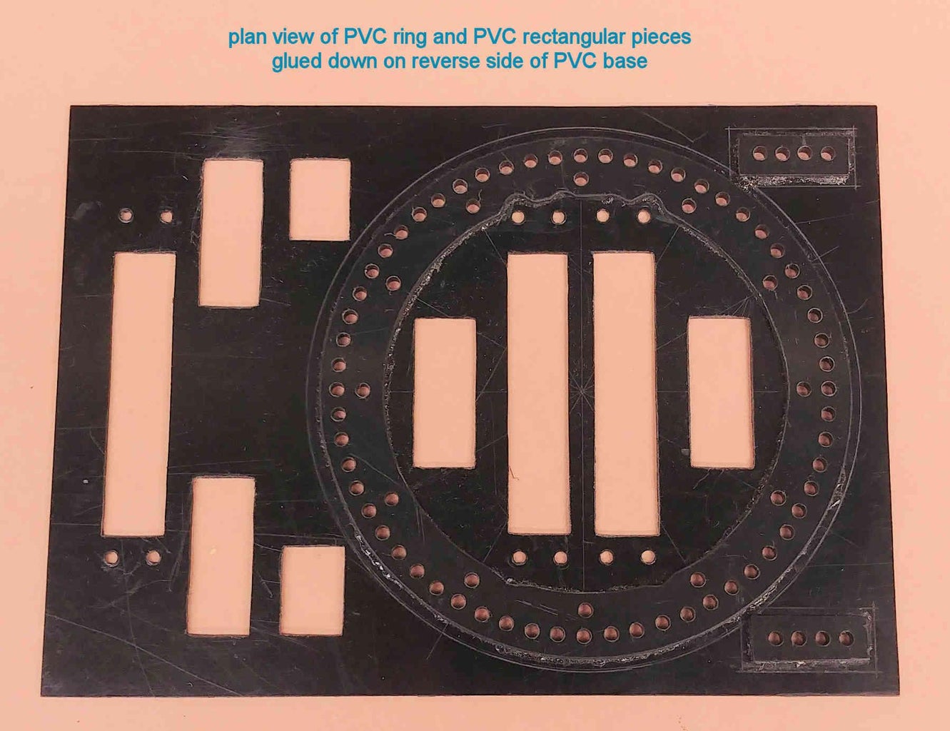
Out of the 1mm thick PVC sheet, cut 2 ring shaped pieces, each with an outer diameter of 115.5mm, and an inner diameter of 88.5mm. A rotary tool (eg. a Dremel) will help enormously here, and will be a huge time saver. Alternatively, use some scissors, a drill, and a file. Glue the 2 PVC rings together using PVC adhesive to make a single ring 2mm thick.
On the reverse side of the 131mm x 181mm PVC base find the centre point of the sixty 1mm diameter holes that are arranged in a circular fashion. This can easily be done by drawing a vertical line between the two 1mm diameter holes at the 12 o'clock and 6 o'clock positions, followed by a horizontal line between the two 1mm diameter holes at the 3 o'clock and 9 o'clock positions. Where the 2 lines cross is the centre point. Using a compass, score a circle of radius 60mm about this centre point as shown in the photo.
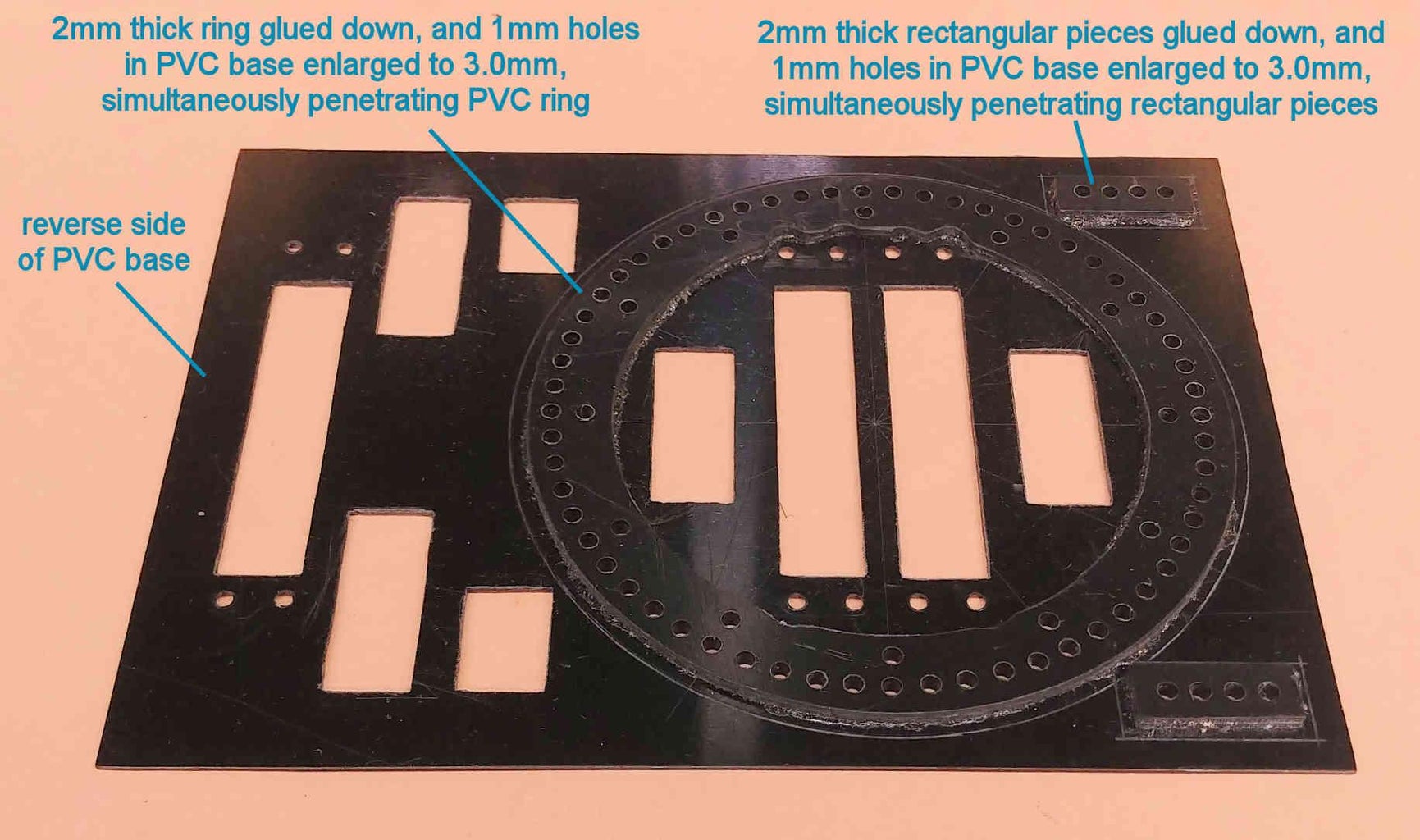
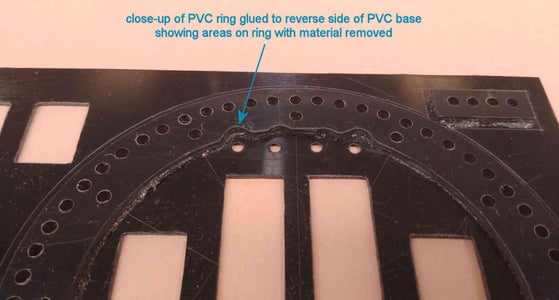
Place the 2mm thick PVC ring central to this centre point on the reverse side of the PVC base. The previously scored 60mm radius circle will aid in this (ie. ensure that the distance from the outer edge of the 2mm thick ring to the scored circle is constant around the entire circumference). Notice how the 2mm thick ring is either very close to or partially obscuring the four 2mm diameter countersunk holes to the right of the two 62mm x 13mm rectangular cut outs. File away some of the 2mm thick PVC ring around these four 2mm diameter holes such that the PVC ring is at least 2.5mm away from the edge of these four holes. Central to the centre point of the sixty 1mm diameter holes, glue the 2mm thick PVC ring onto the reverse side of the PVC base, ensuring that the four filed away areas of the PVC ring align with the previously mentioned four 2mm diameter countersunk holes.
Out of the 1mm thick PVC sheet, cut four rectangular pieces of dimensions 9mm x 24mm. Glue one of the pieces directly on top of another piece to end up with two, 2mm thick rectangular pieces of dimensions 9mm x 24mm. Score a rectangle of size 13mm x 28mm centrally around each of the 4 vertically arranged 1mm holes on the reverse side of the 131mm x 181mm PVC base as shown in the photo. Glue each of the 2mm thick, 9mm x 24mm PVC rectangular pieces centrally within the 13mm x 28mm scored rectangles surrounding the 4 vertically arranged 1mm diameter holes on the reverse side of the PVC base.
Enlarge the eighty 1mm diameter holes in the PVC base to a 3.0mm diameter, drilling straight through the glued on 2mm thick PVC ring and the 2mm thick rectangular PVC pieces. These holes should be a push fit for the 60 yellow, 12 pink, and 8 white LEDs that will be populating them. I strongly recommend that before you enlarge these 1mm diameter holes you do a quick test first as you can't go back if you make the holes too big. This test involves gluing 3 small pieces of the 1mm thick PVC sheet together to form a single piece 3mm thick, and then drilling a 3.0mm diameter hole into it, checking that the yellow, pink, and white LEDs are indeed a push fit when fully inserted into the 3.0mm diameter hole.
Step 7: Filing Down 3mm (dome Top) LEDs
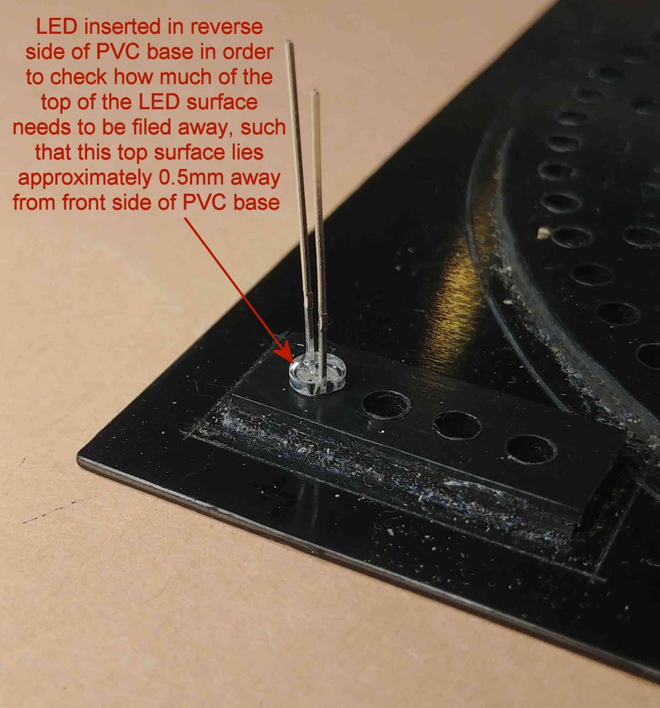
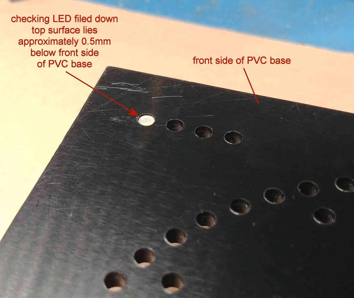
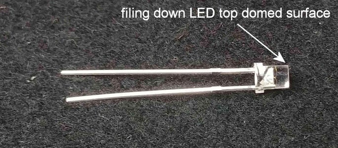
File approximately 1mm off the (domed) top of the 60 yellow, 12 pink, and 8 white LEDs to form flat topped LEDs, such that when the LEDs are fully inserted (from the reverse side) into the 3.0mm diameter holes in the PVC base, the top of the LEDs are just below (approximately 0.5mm) the front side of the PVC base. Once the LEDs have been filed to size, lightly run the flat topped LED surfaces across a piece of 300-400 Grit sanding sheet a few times to smooth the surface finish.
Step 8: Creating the Front Fascia
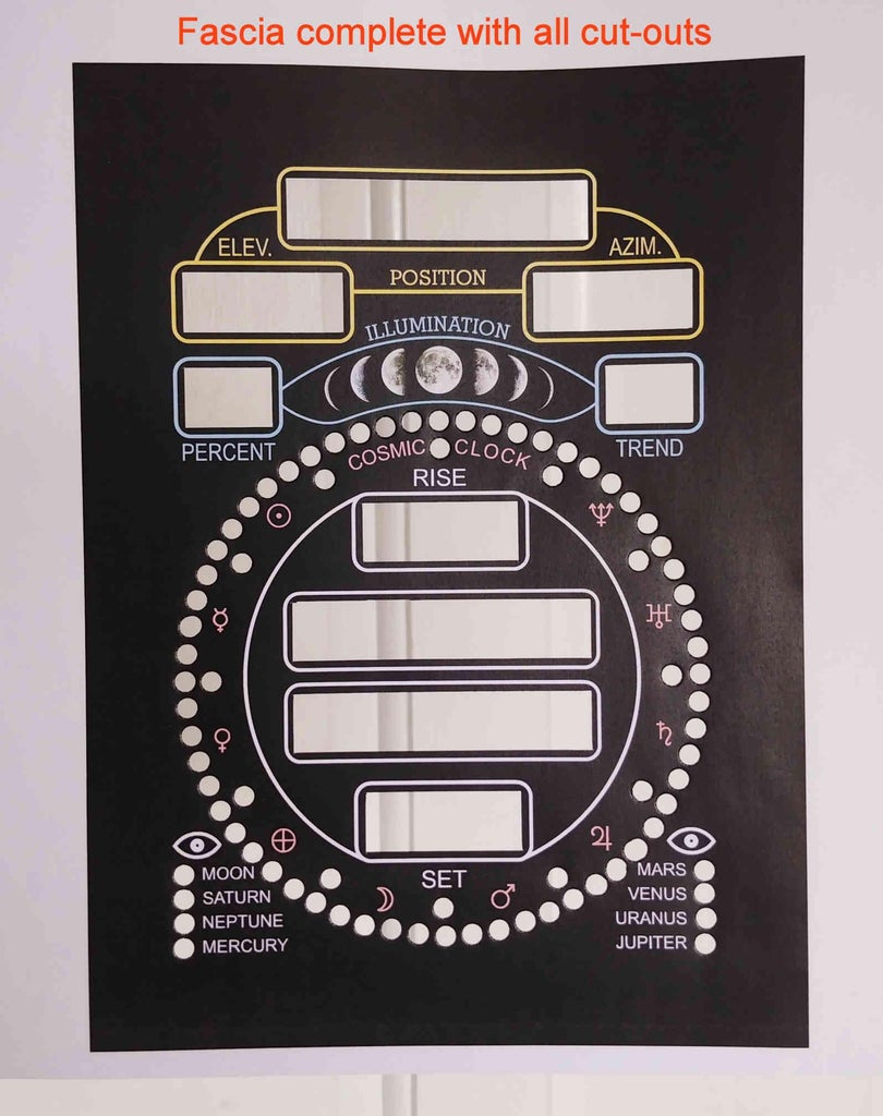
Print at 100% size (not 'fit to page') the file print_on_A4_white_paper.pdf onto an A4 white sheet of paper of thickness 90-100gsm. This printed paper will become the front fascia.
Using a sharp scalpel cut the 9 thin lined yellow rectangles (within the 9 yellow, blue, and white rounded edged rectangles) out of the paper fascia, as shown in the photo. (No trace of the yellow lines making up the rectangles should now exist on the paper fascia).
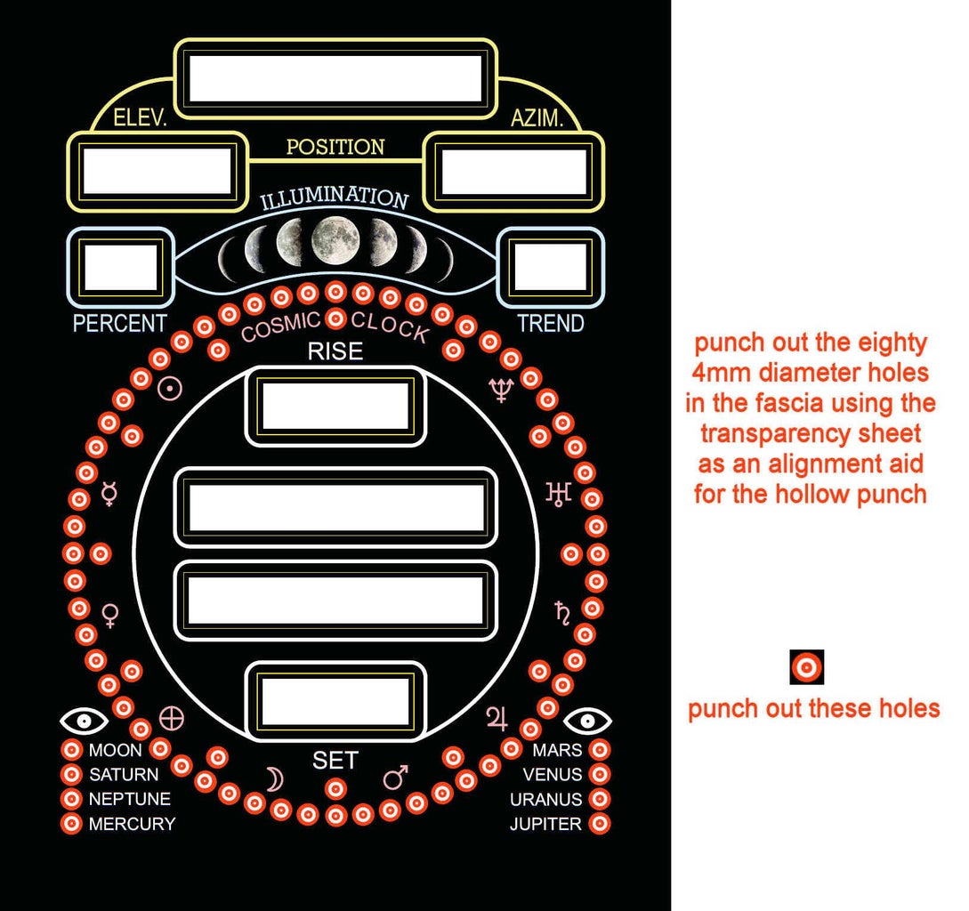
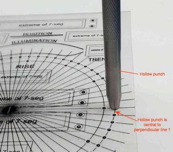
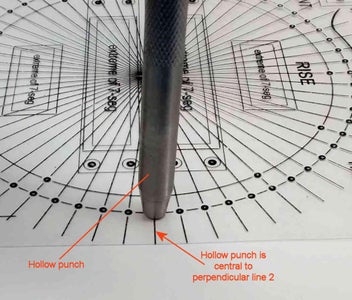
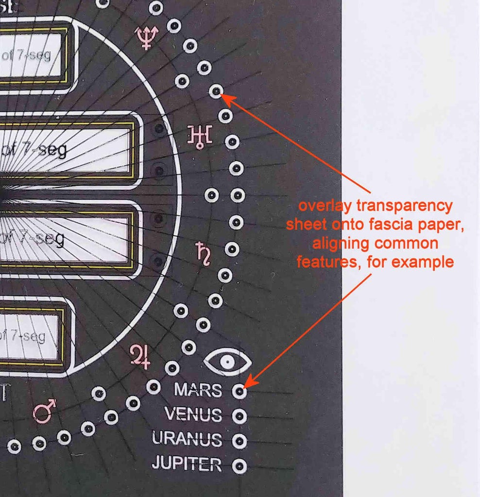
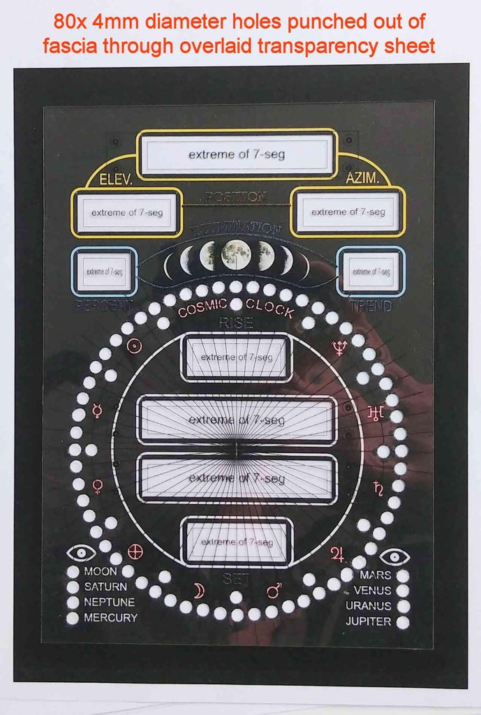
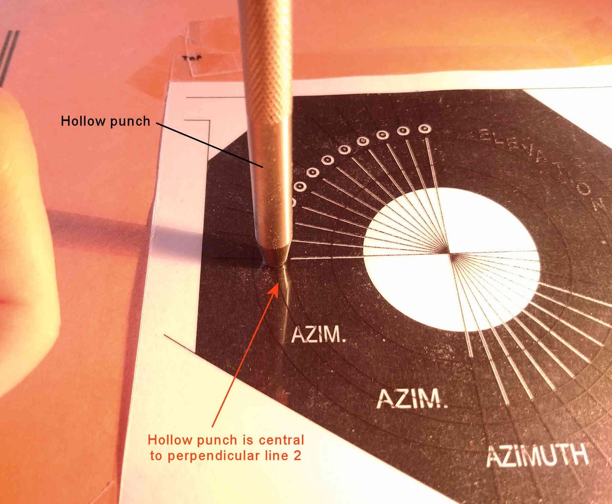
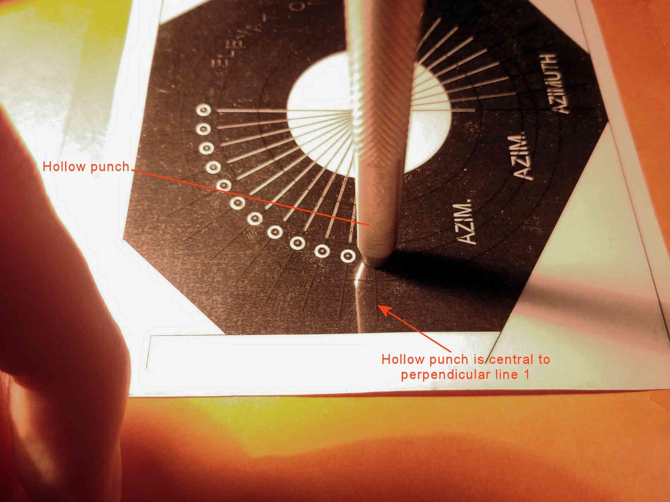
Overlay the transparency sheet onto the paper fascia, aligning the artwork on the transparency with the common features on the paper fascia. Tape down the transparency sheet around its edges onto the paper fascia to prevent it from moving. Using a 5/32" or a 4mm hollow punch, together with a hammer, punch out of the paper fascia the eighty circles that coincide with the location of the (to be fitted) 3mm LEDs. Perpendicular lines on the transparency sheet indicate the centre of each circle on the fascia along two directions, and will help to align the hollow punch exactly over the centre of each circle (as the hollow punch will naturally obscure the circle when placed centrally over it). It is therefore critical, when placing the hollow punch over each circle, to ensure that the end of the hollow punch lies centrally to these two perpendicular lines when looking from two directions, as shown in the photo. It is also strongly recommended to have either a piece of card or several layers of paper beneath the paper fascia to ensure clean holes are punched out of the paper fascia.
Overlay the completed paper fascia onto the 131mm x 181mm PVC base and check that the circular holes and rectangular cutouts in the paper fascia align with the corresponding holes and rectangular cutouts in the PVC base. For aesthetic reasons only, there should be no PVC material visible around the areas of the rectangular cutouts in the paper fascia (ie. the rectangular cutouts in the PVC base should be very slightly larger than the cutouts in the paper fascia).

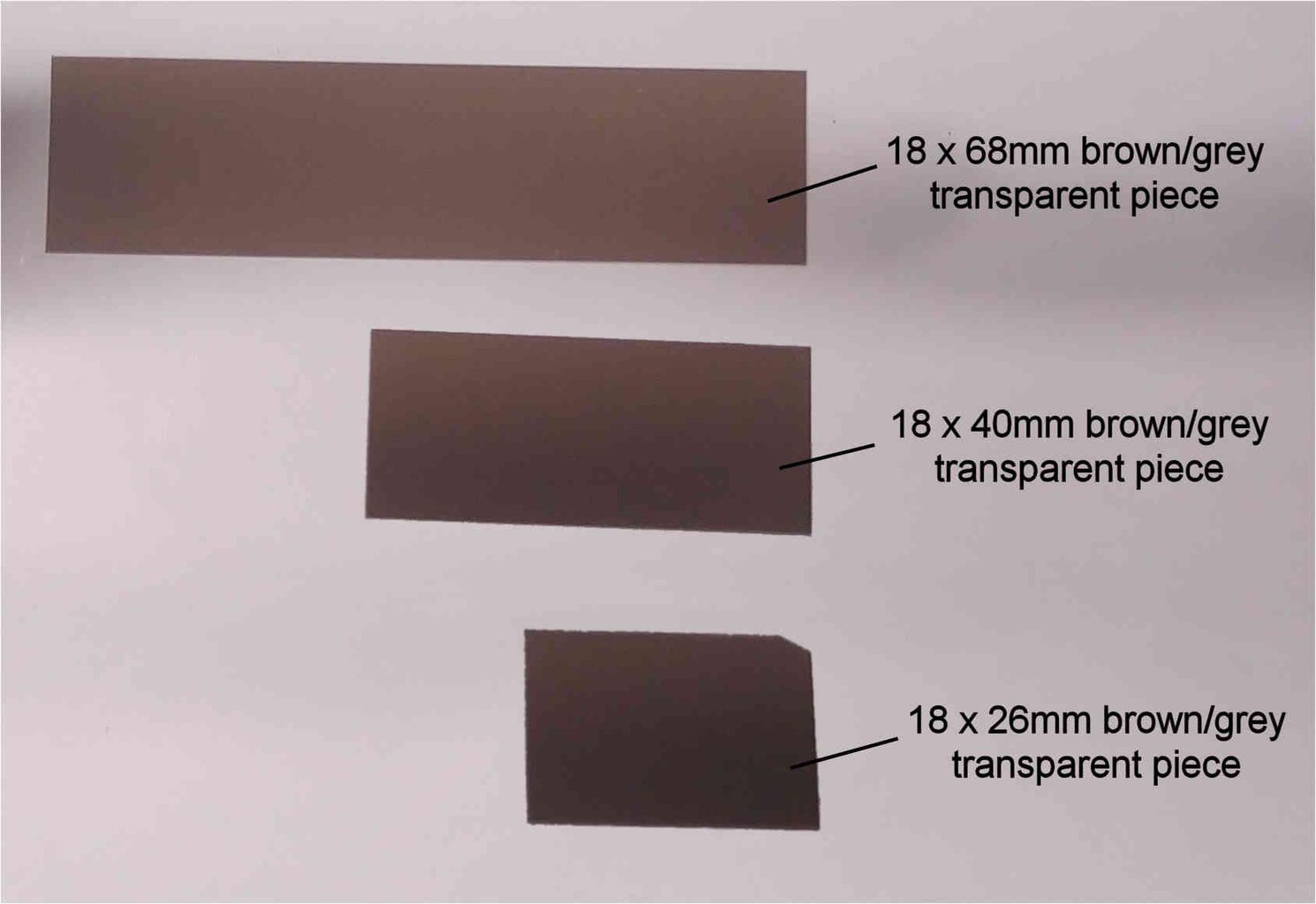
Step 9: Contrast Enhancing Filters for 7-segment Displays
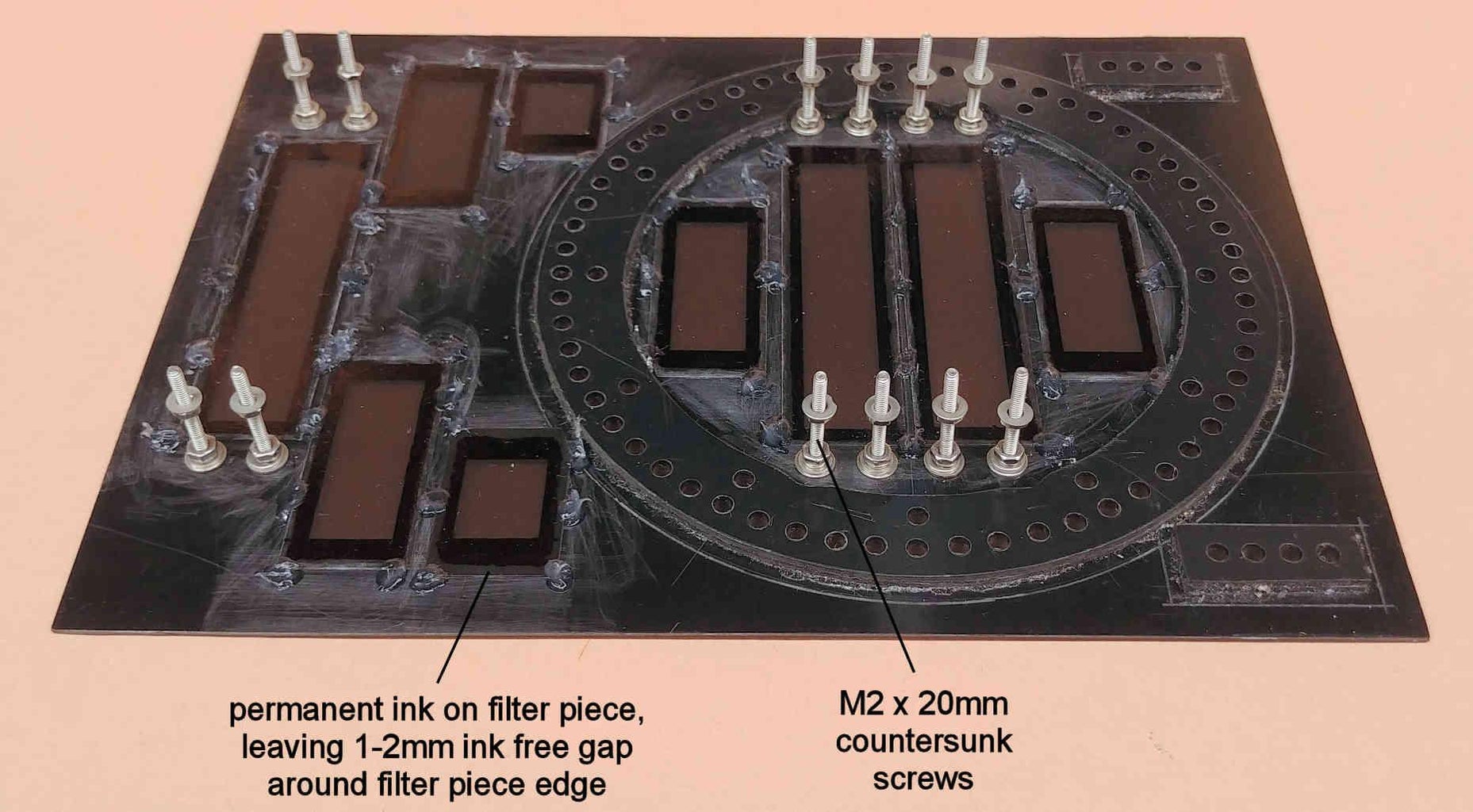
Fit the twelve M2 x 20mm long countersunk screws through their countersunk holes in the PVC base, and fix in place using one M2 plain washer, one M2 spring washer, and one M2 nut for each screw.
From the 0.1 to 0.2mm thick, relatively heavily tinted, grey or brown transparent sheet, cut two pieces of size 18mm x 26mm, four pieces of size 18mm x 40mm, and three pieces of size 18mm x 68mm. These transparent pieces will act as contrast enhancing filters for the 7-segment displays in bright ambient light conditions, so that the difference between unlit and lit segments on the displays is clearly visible. Whatever transparent sheet you use, check first that it is NOT so heavily tinted that the display becomes too dim to read in very dark or very bright ambient light conditions. Here in the UK, some of the divider pages of some Pukka Pad notebooks contain relatively heavily tinted brown transparent sheets which are ideal to use.
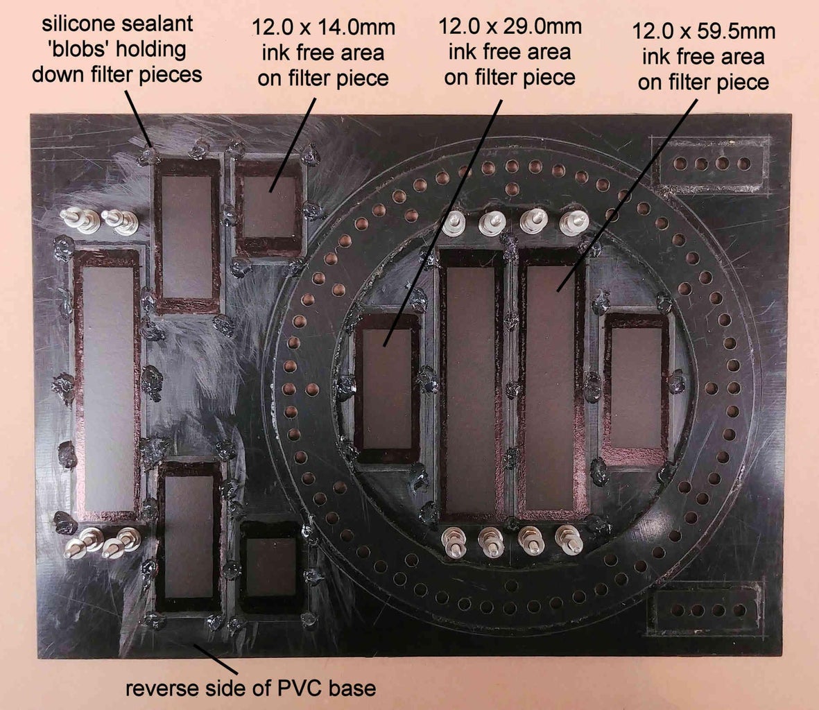
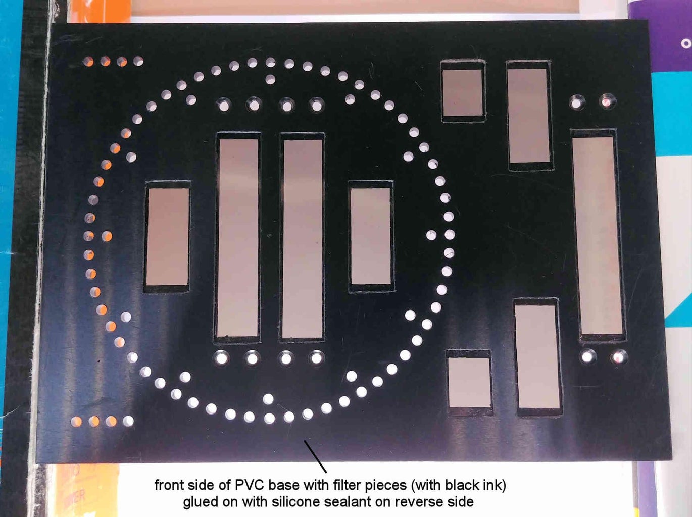
Glue down these 9 transparent grey or brown pieces centrally over the 9 rectangular cut-outs on the reverse (inner) side of the PVC base, but ONLY in a few locations around the edges of the transparent sheets. Ensure that NO glue encroaches into the area of the transparent pieces that the front face of the various 7-segment displays will touch. I have used Dowsil 732 silicone sealant (acting as a light, flexible adhesive) for this purpose, smearing a small blob of it simultaneously over a small area of the transparent grey/brown filter, and across onto a small area of the adjacent PVC base (as shown in the photo). The main holding strength for the grey/brown transparent filters will come from an epoxy adhesive applied later on.
Optionally, for aesthetic reasons, (and best done before the filter pieces are glued in place,) using a permanent fine tipped black marker pen, cover the inner face of the grey/brown contrast filter with black ink in areas that the actual segments making up the 7-segment displays are not in contact with, except for an area say 1-2mm in width around the outer edge of the grey/brown filter, to allow for a good adhesion for the glue. Sizes for the centrally located rectangles on the pieces of grey/brown filter that are BLACK INK FREE are 12.0mm x 14.0mm for the 18mm x 26mm sized filter piece, 12.0mm x 29.0mm for the 18mm x 40mm sized filter piece, and 12.0mm x 59.5mm for the 18mm x 68mm sized filter piece.
Step 10: Gluing Down the 7-Segment Displays
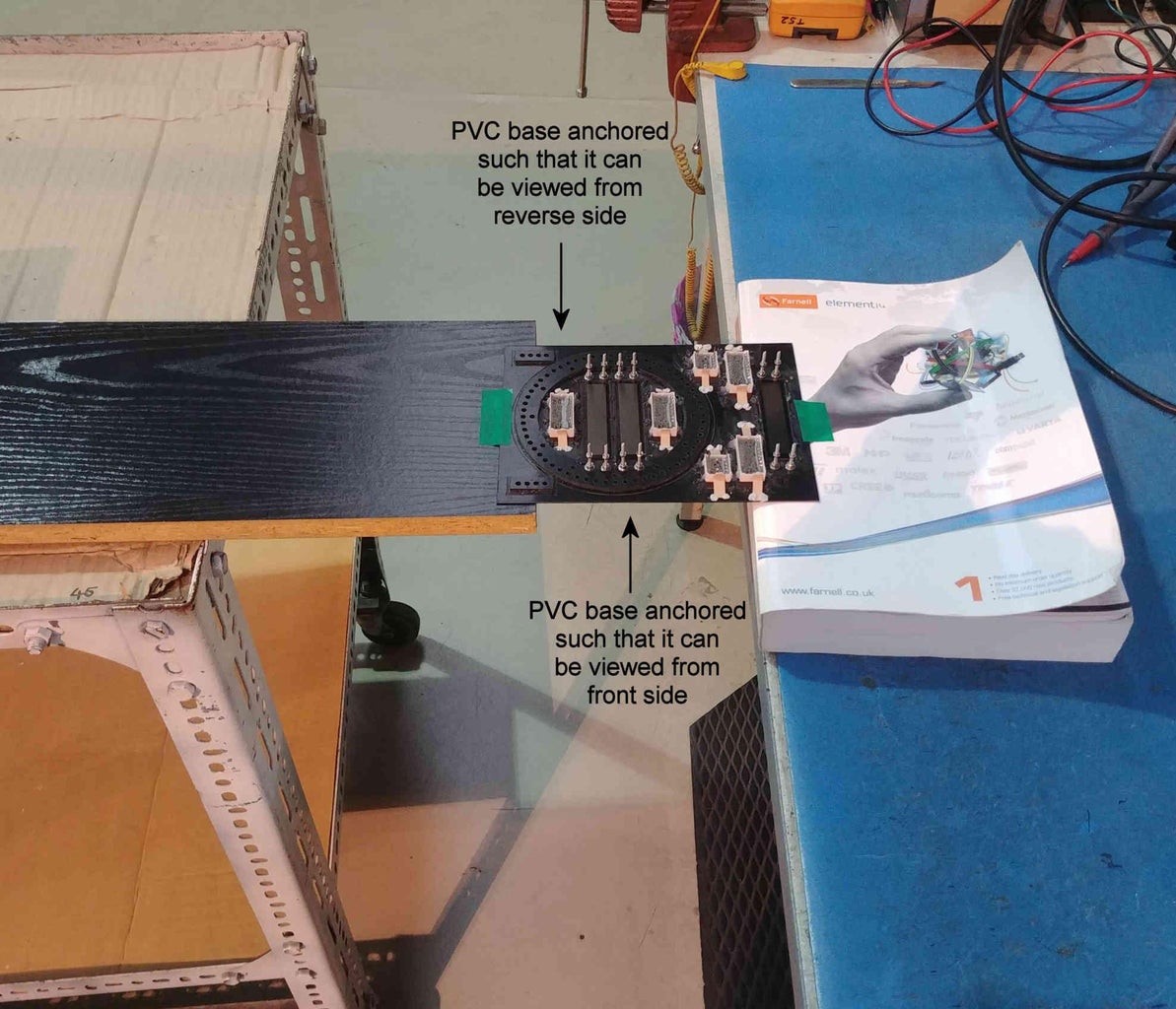
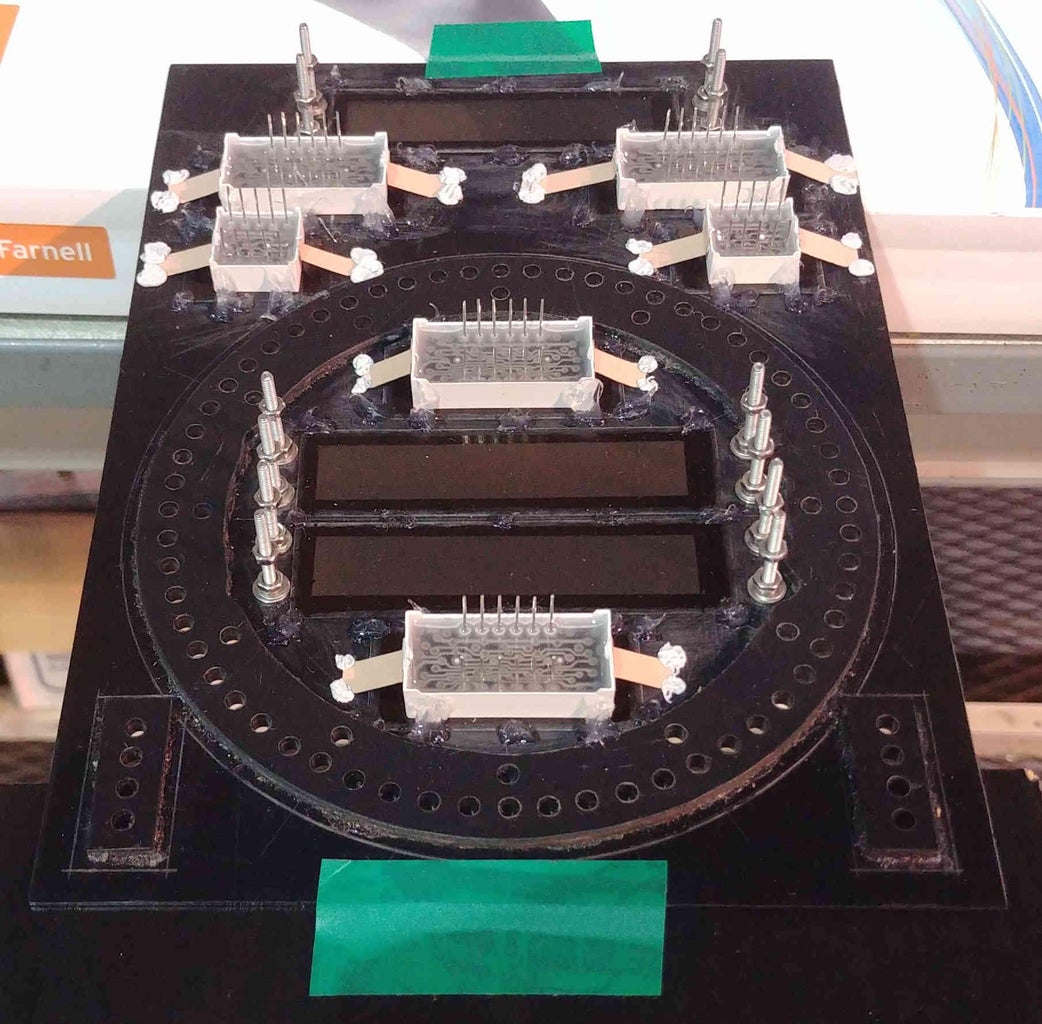
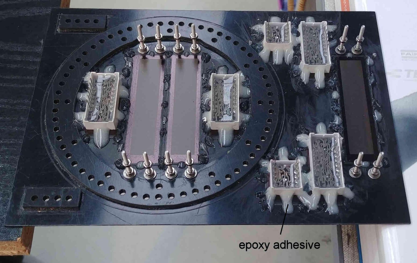
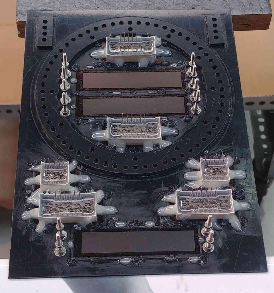
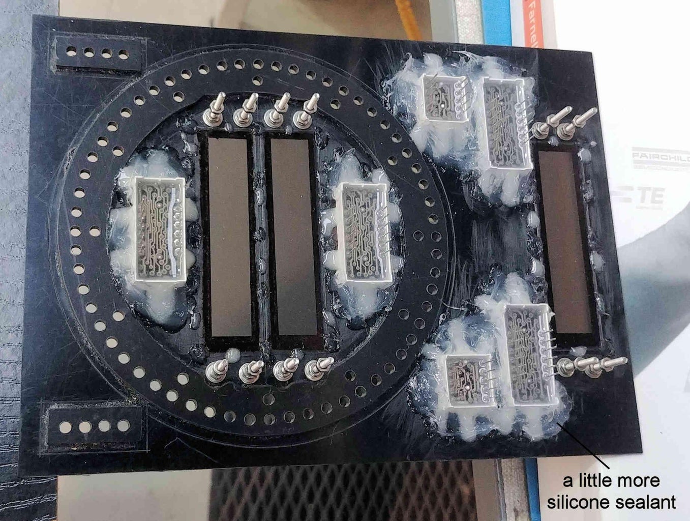
Note, during this step it is best to fix and balance the PVC base in such a way that both its front and reverse sides can be viewed easily (see attached photo).
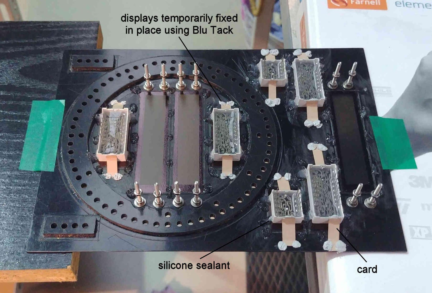
Place one of the 4-digit seven segment displays centrally over the non-inked out area on the contrast enhancing filter piece, and temporarily fix in it in place with some Blu Tack and a little card attached to both the 4-digit display and the PVC base (see attached photo).
Apply some Dowsil 732 silicone sealant (acting as a flexible adhesive) in small areas a few mm wide both across the side walls of the 4-digit display (close to its corner), and across the contrasting enhancing filter piece and neighbouring PVC base. Once the silicone sealant has fully cured, carefully remove the applied Blu Tack and card from the 4-digit display and PVC base, and remove any residual grease from where the Blu Tack was in contact with the 4-digit display and PVC base using a little pure alcohol soaked into a tissue.
In a similar fashion to the application of the silicone sealant, apply some 2-part epoxy adhesive in small areas a few mm wide both across the side walls of the 4-digit display, and across the contrast enhancing filter piece and neighbouring PVC base (see attached photo). Remaining visible areas of the side wall of the 4-digit display are again covered with silicone sealant, the silicone sealant also being spread to adjacent areas of the contrast enhancing filter and PVC base (see attached photo).
Repeat this fixing procedure for the remaining three 4-digit displays, and the two 2-digit displays.
Step 11: Retaining Pieces for PVC Base
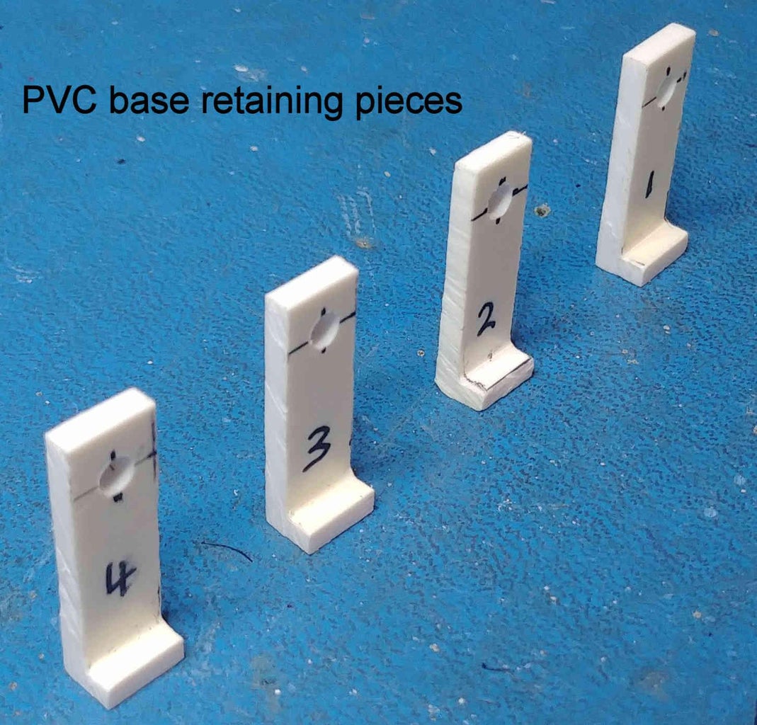
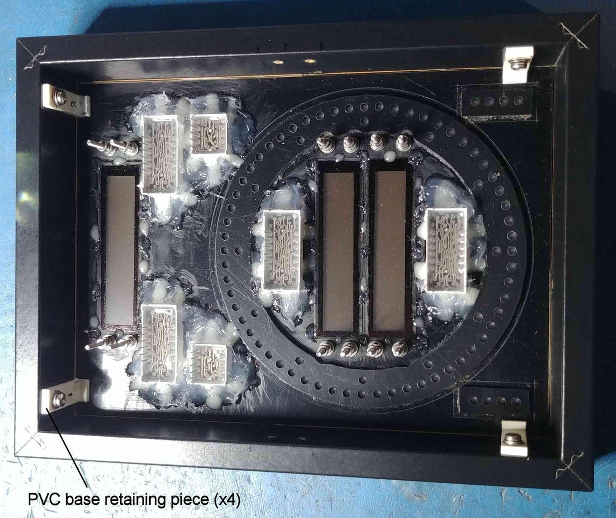
Place the plastic transparent window into the front photo frame. On top of this window place firstly a sheet of paper with the same thickness as the paper fascia, and then the PVC base.
As shown in the attached photos, use 4 short pieces of 2-3mm thick plastic, together with No.4 x 3/8" self tapping screws to retain the PVC base in position. It is highly advisable before fitting the self tapping screws to use a mini pin vise to drill 2mm diameter, 7mm deep pilot holes from the inside of the photo frame. This will minimise any chances of the frame splitting when the screws are inserted. Be very careful that this 2mm diameter pilot hole does not penetrate the outer frame surface.
Step 12: Fitting the 8-Digit MAX7219 Displays and 3mm LEDs
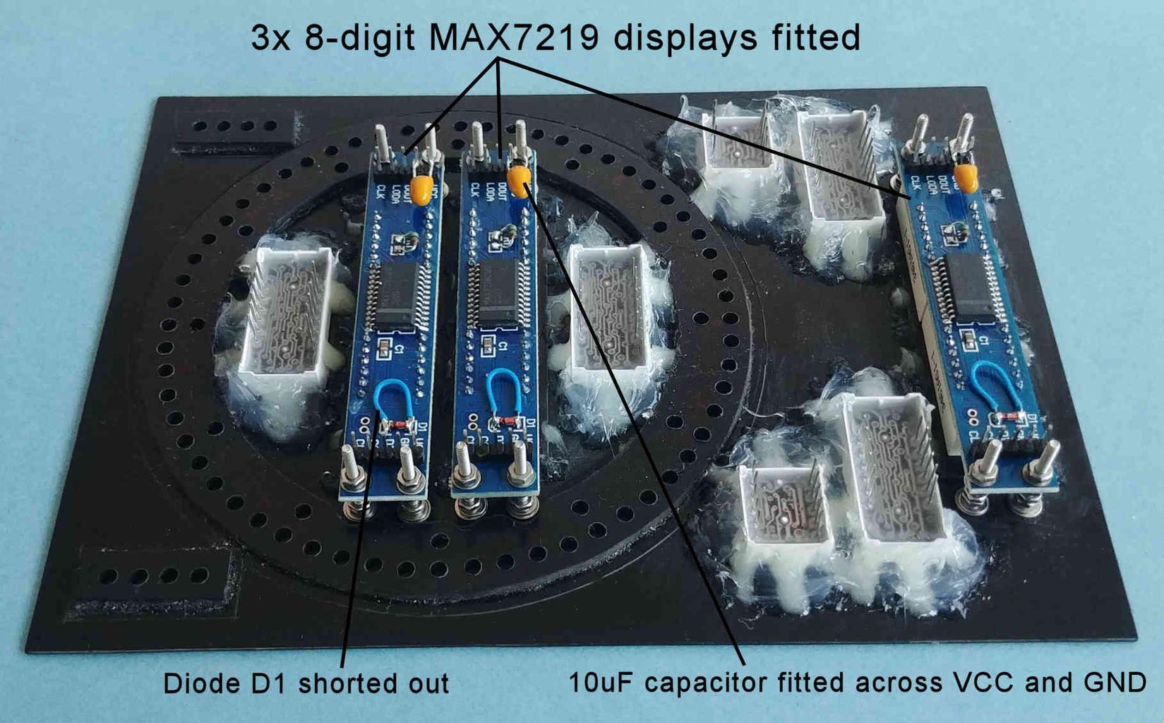
On each of the three 8-digit MAX7219 displays, short out diode D1 with a piece of wire, and fit a 10uF tantalum capacitor across VCC and GND.
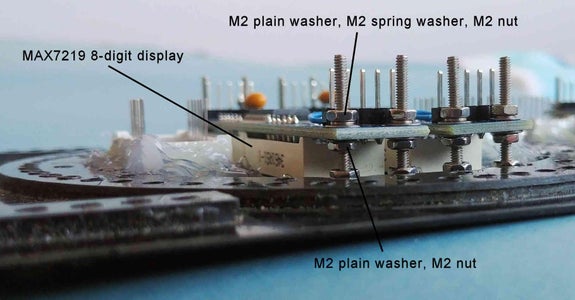
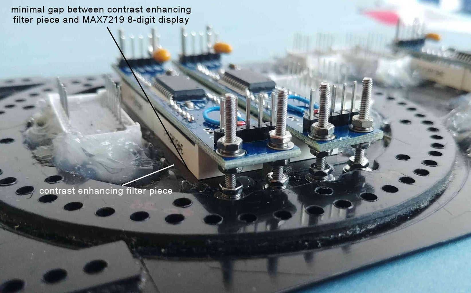
For each of the twelve M2 x 20mm long countersunk screws fit an M2 nut approximately half way down its length, and then fit an M2 plain washer on top of the nut. Place the three 8-digit 7-segment displays over these M2 countersunk screws so that they are resting on the M2 plain washers half way down their lengths. Each of the M2 nuts sitting half way down the M2 countersunk screws are now wound further down the screws lengths such that the faces of the 8-digit 7-segment displays are now just a fraction of a millimeter above the contrast enhancing filter pieces. Once the 8-digit 7-segment displays are in the correct position (just above the filter pieces), fit a further M2 plain washer, followed by an M2 spring washer and M2 nut onto each M2 countersunk screw, and tighten the M2 nut up so that the 8-digit 7-segment displays are 'sandwiched' in place between two M2 washers, an M2 spring washer, and two M2 nuts. See attached photos for details.
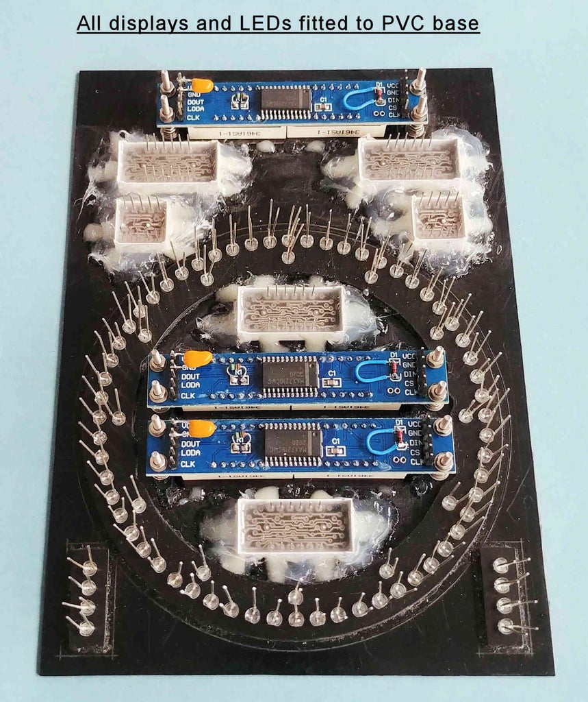
Fit the filed down 3mm Yellow, pink, and white LEDs from STEP 7 into the holes in the PVC base.
Step 13: OPTIONAL - Constructing the Elevation and Azimuth Planet/Sun/Moon Pointers
This is the most challenging part of the Instructable, and it will be of great help if you have access to a lathe to produce the single PVC piece making up the Azimuth pointer, and the three PVC pieces making up the Elevation pointer. If you don't have access to a lathe then it is possible to produce these pieces if you have a rotary tool (eg, a Dremel), and can source short pieces of PVC rod of diameters 30mm and 83mm (these dimensions not being critical). Alternatively, you could always 3D print these parts.
Elevation Pointer
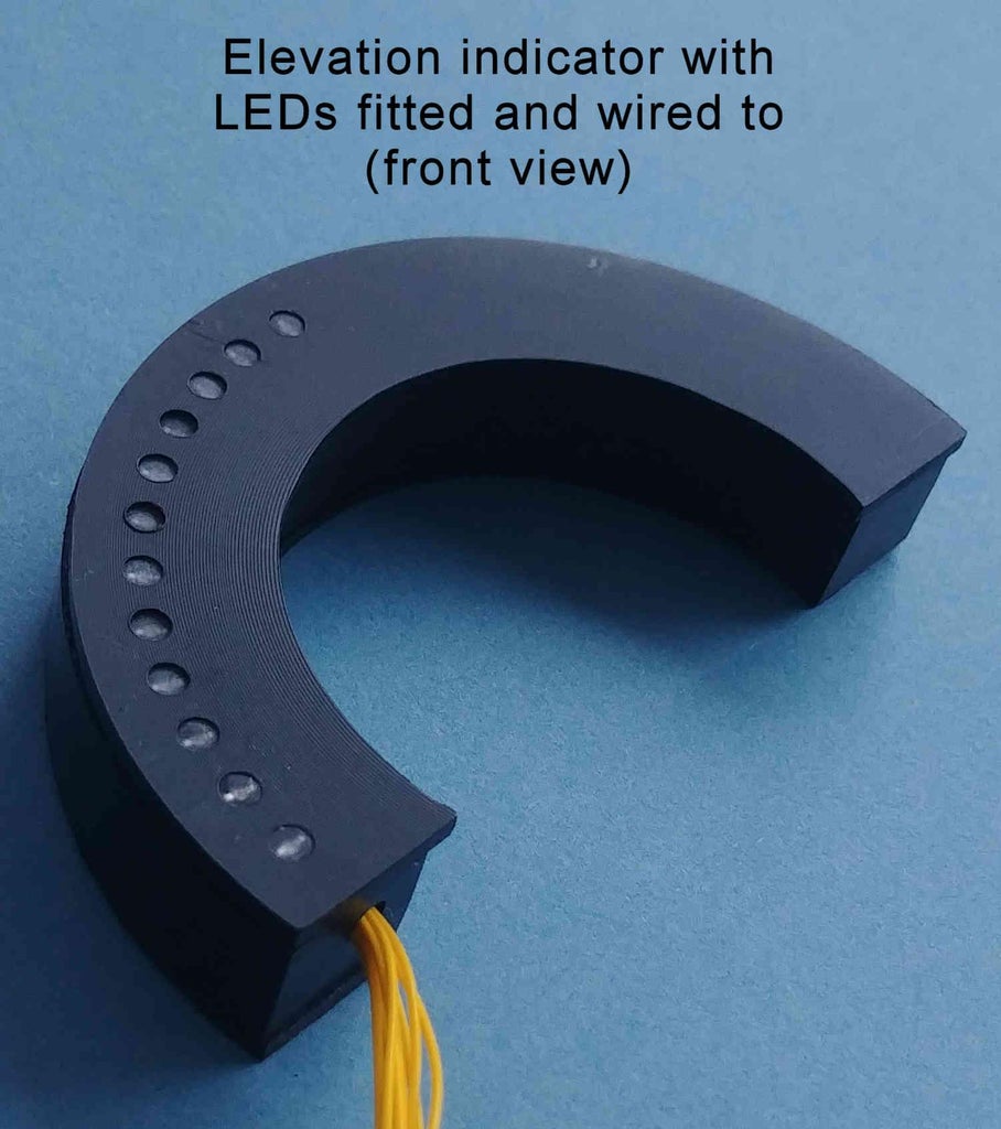
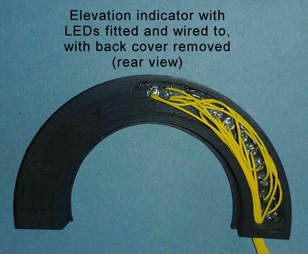
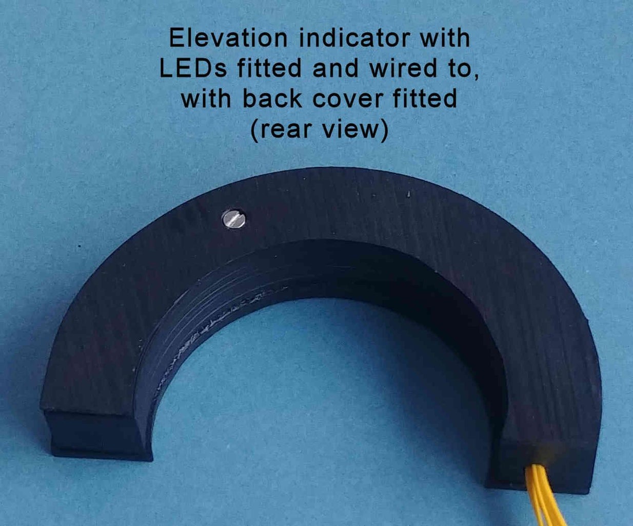
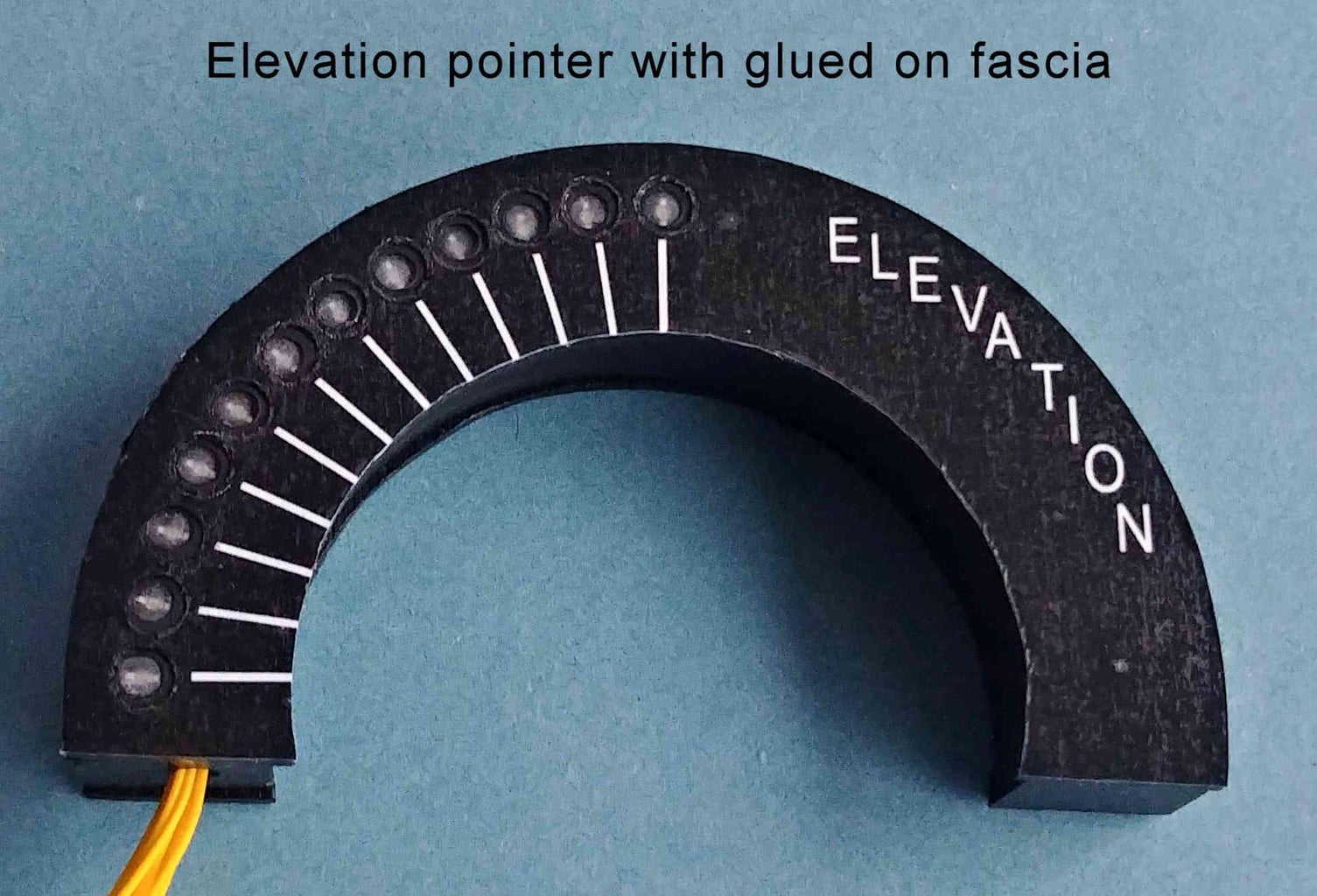
Mechanical details of the three PVC pieces making up the optional (top photo frame mounted) Elevation pointer is found in the attached file Elevation_mechanical_pointer.pdf. Piece 2 is screwed into the rear side of Piece 1, whilst Piece 3 is glued onto the front side of Piece 1.
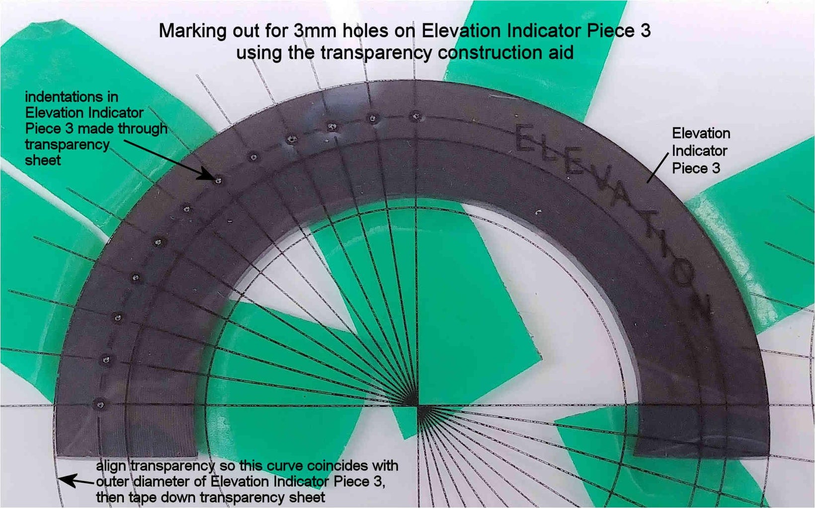
In order to help locate the 12 positions on Piece 3 that have 3.0mm diameter through holes, print out at 100% size (not 'fit to page') the file Elevation_pointer_helper-print_on_A4_transparency.pdf onto an A4 transparency sheet. Overlay this transparency sheet onto Piece 3, aligning the outer curve on the transparency with the outer diameter of Piece 3, as shown in the attached photo. Tape down the transparency sheet onto Piece 3 to prevent it from moving. Push a sharp point (eg. the point on a compass) through the centre of the 12 circles on the transparency sheet so that an indentation is made in the PVC base below. Remove the transparency sheet from Piece 3. The 12 indentations in Piece 3 are the locations that the 3.0mm diameter holes should be drilled. IMPORTANT. In a similar fashion to that in STEP 6, before drilling the twelve 3.0mm diameter holes in the Elevation LED pointer, ensure that the red LEDs that will populate these holes are a push fit into them, as you can't go back if you make the holes too big. Once the holes have been drilled, in a similar fashion to that in STEP 7, file approximately 1mm off the top of the 12 red LEDs to form flat topped LEDs, such that when the LEDs are fully inserted into the 3.0mm diameter holes, the top of the LEDs are just below (approximately 0.5mm) the front surface of the Elevation pointer. Once the LEDs have been filed to size, lightly run the flat topped LED surfaces across a piece of 300-400 Grit sanding sheet a few times to smooth the surface finish. It is strongly advisable that due to space constraints the electrical connections are made to the 12 LEDs before they are finally inserted into the Elevation pointer.
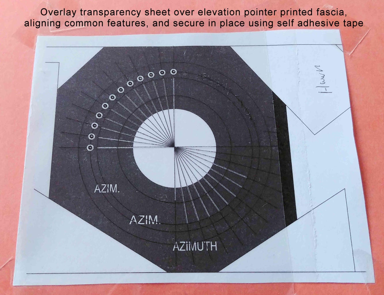
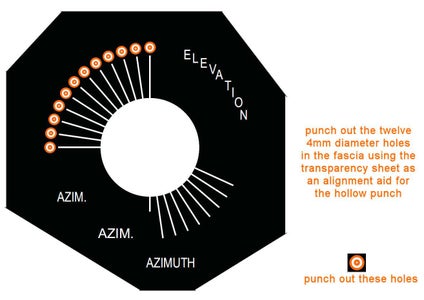
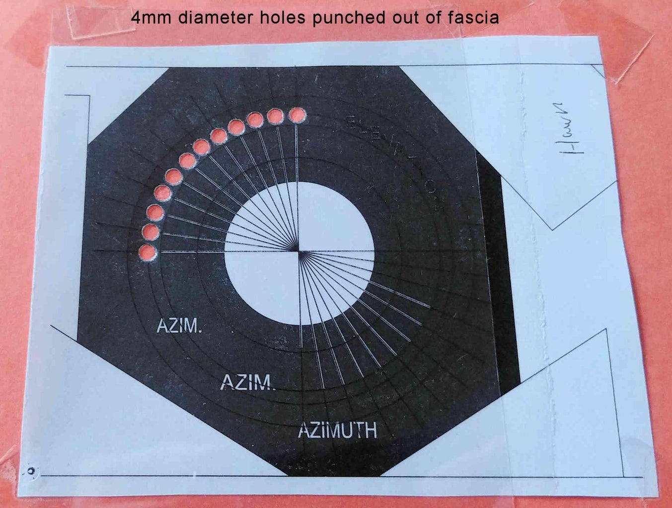
Print out at 100% size (not 'fit to page') the file Elevation_pointer_fascia_print_on_A4_paper.pdf onto an A4 white sheet of paper of thickness 90-100gsm. This printed paper will become the Elevation pointer fascia. You can choose whether to use the fascia without the word ELEVATION on it, or to use the fascia with the word ELEVATION on it. Optionally apply a sheet of self adhesive book covering film onto the printed out paper fascia to protect it. Overlay the transparency sheet onto the paper fascia, aligning the artwork on the transparency with the common features on the paper fascia. Tape down the transparency sheet around its edges onto the paper fascia to prevent it from moving. Using a 5/32" or a 4mm hollow punch, together with a hammer, punch out of the paper fascia the 12 circles that coincide with the location of the (to be fitted) 3mm LEDs. Perpendicular lines on the transparency sheet indicate the centre of each circle on the fascia along two directions, and will help to align the hollow punch exactly over the centre of each circle (as the hollow punch will naturally obscure the circle when placed centrally over it). It is therefore critical, when placing the hollow punch over each circle, to ensure that the end of the hollow punch lies centrally to these two perpendicular lines when looking from two directions, as shown in the attached photo. It is also strongly recommended to have either a piece of card or several layers of paper beneath the paper fascia to ensure clean holes are punched out of the paper fascia.
Once the 12 holes have been punched out of the Elevation pointer fascia, stick the fascia onto the front of Elevation pointer using a glue stick, ensuring that the 12 holes in the fascia align with the 12 holes in the front of the Elevation pointer. After the glue has set, using a scalpel, cut away any overhanging paper that is not in contact with the front of the Elevation pointer.
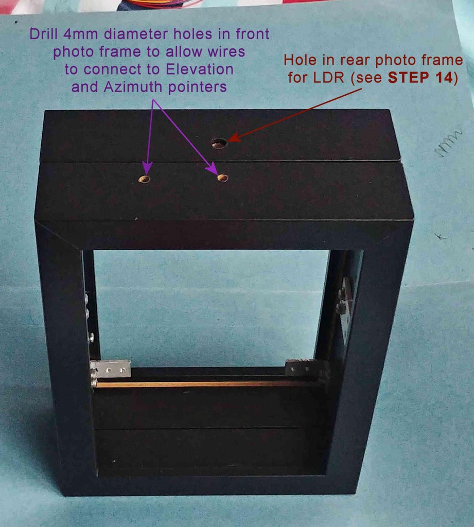
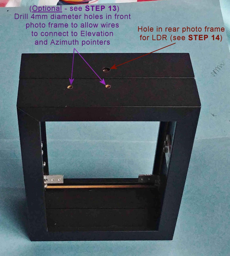
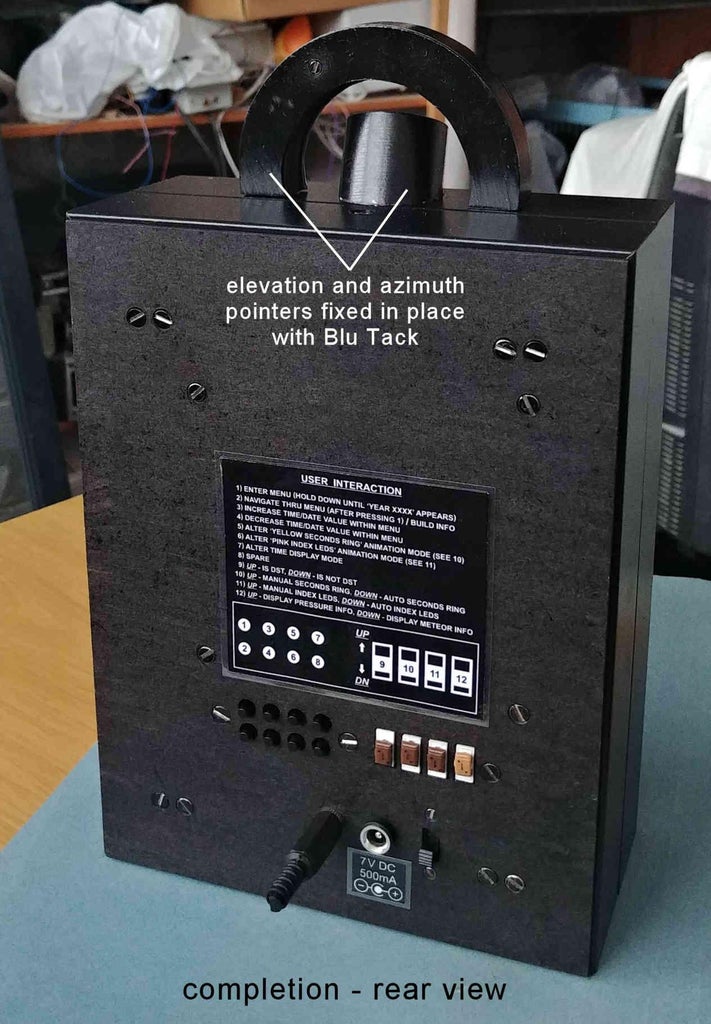
Drill a 4mm diameter hole through the top of the front photo frame to allow the electrical wiring to connect to the Elevation pointer - see attached photo. The Elevation pointer itself is simply held in place to the top of the photo frame with Blu Tack (reusable adhesive putty) or permanent glue.
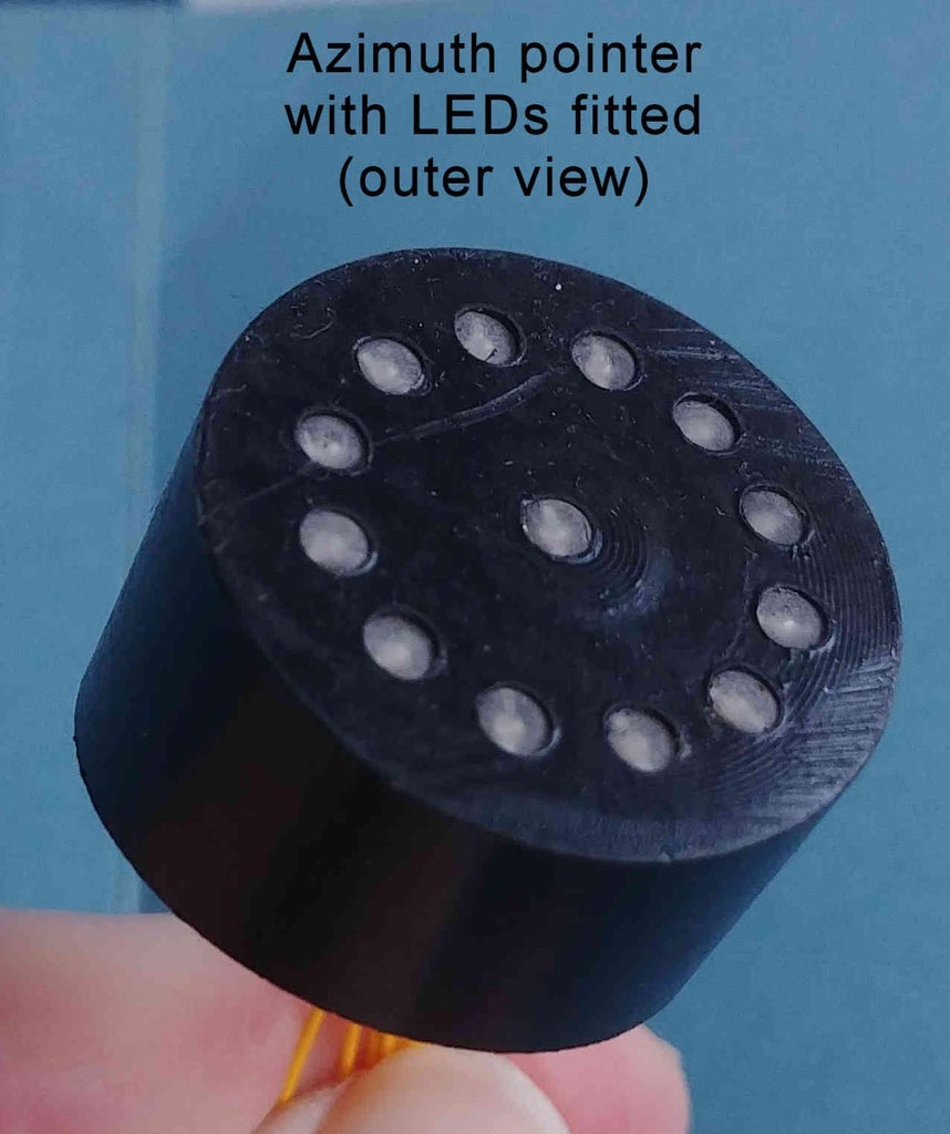
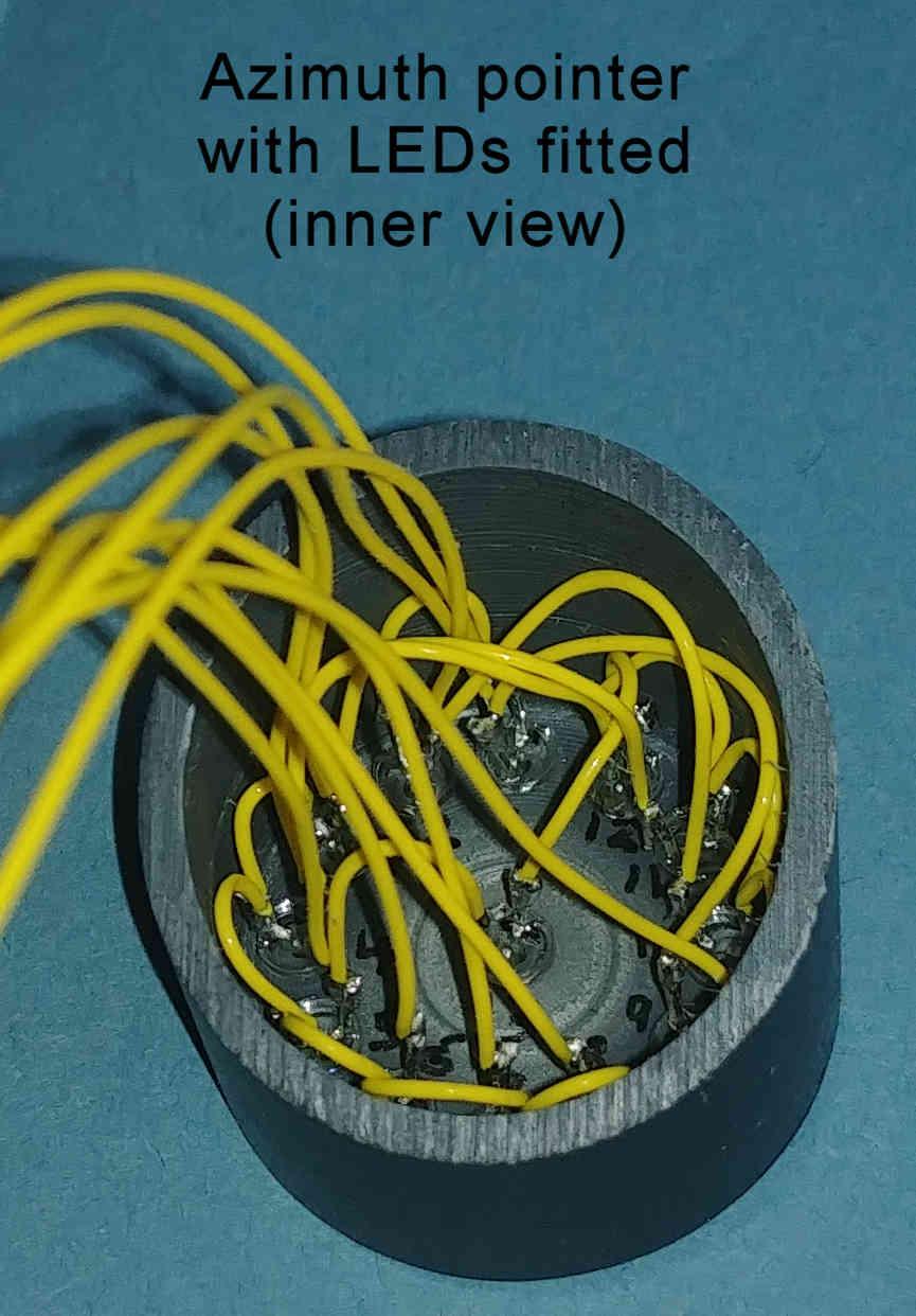
Azimuth Pointer
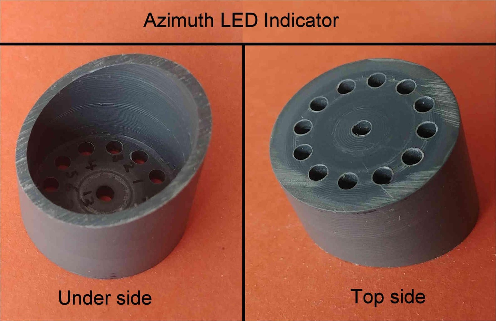
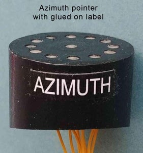
Mechanical details of the single PVC piece making up the optional (top photo frame mounted) Azimuth pointer is found in the attached file Azimuth_mechanical_pointer.pdf.
IMPORTANT. In a similar fashion to that in STEP 6, before drilling the thirteen 3.0mm diameter holes in the Azimuth LED pointer, ensure that the yellow LEDs that will populate these holes are a push fit into them, as you can't go back if you make the holes too big. Once the holes have been drilled, in a similar fashion to that in STEP 7, file approximately 1mm off the top of the 13 yellow LEDs to form flat topped LEDs, such that when the LEDs are fully inserted into the 3.0mm diameter holes, the top of the LEDs are just below (approximately 0.5mm) the front side of the Azimuth pointer. Once the LEDs have been filed to size, lightly run the flat topped LED surfaces across a piece of 300-400 Grit sanding sheet a few times to smooth the surface finish. It is strongly advisable that due to space constraints the electrical connections are made to the 13 LEDs before they are finally inserted into the Azimuth pointer.
Optionally, from the previously printed out Elevation pointer fascia, cut out the word AZIMUTH from the paper and stick in onto the front of the Azimuth pointer using a glue stick.
Drill a 4mm diameter hole through the top of the front photo frame to allow the electrical wiring to connect to the Azimuth pointer - see attached photo. The Azimuth pointer itself is simply held in place to the top of the photo frame with Blu Tack (reusable adhesive putty) or permanent glue.
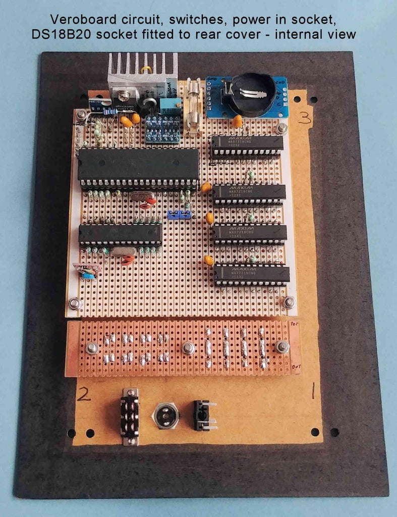
Step 14: Making the Circuit
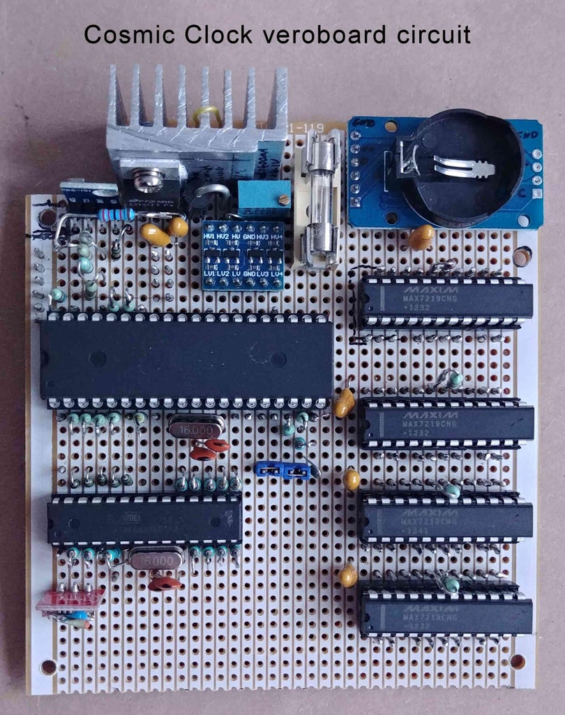
Using a piece of veroboard (stripboard) of approximate size 10cm x 11cm, build the circuit according to the attached schematic Cosmic_Clock_schematic_Rev-A.pdf. The veroboard will be attached to the back cover via M3 countersunk screws, and so provision should be allowed for four 3mm diameter holes to be drilled in the corners of the veroboard.
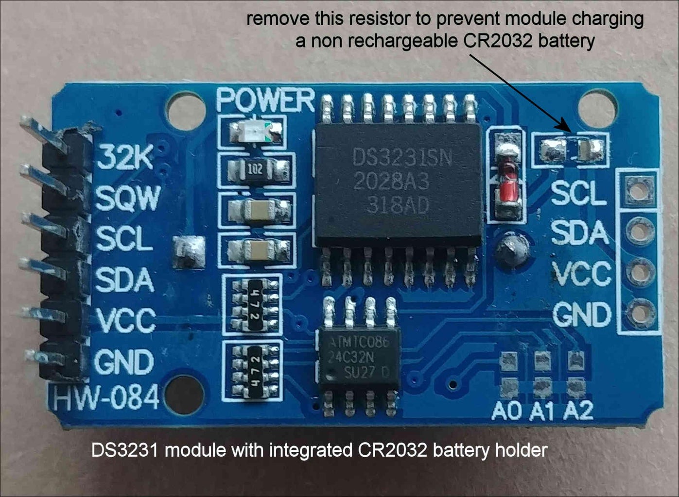
Note1. When fitting the DS3231 module it is important to remove the 200 ohm resistor just above the word 'SCL', and to the right of the DS3231 chip (see attached photo). This is to prevent the module trying to charge a non-rechargeable CR2032 lithium battery (fitted in the battery holder on the module's reverse side) that is used to keep the correct time on power loss.
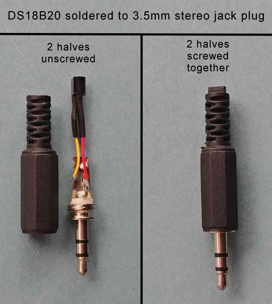
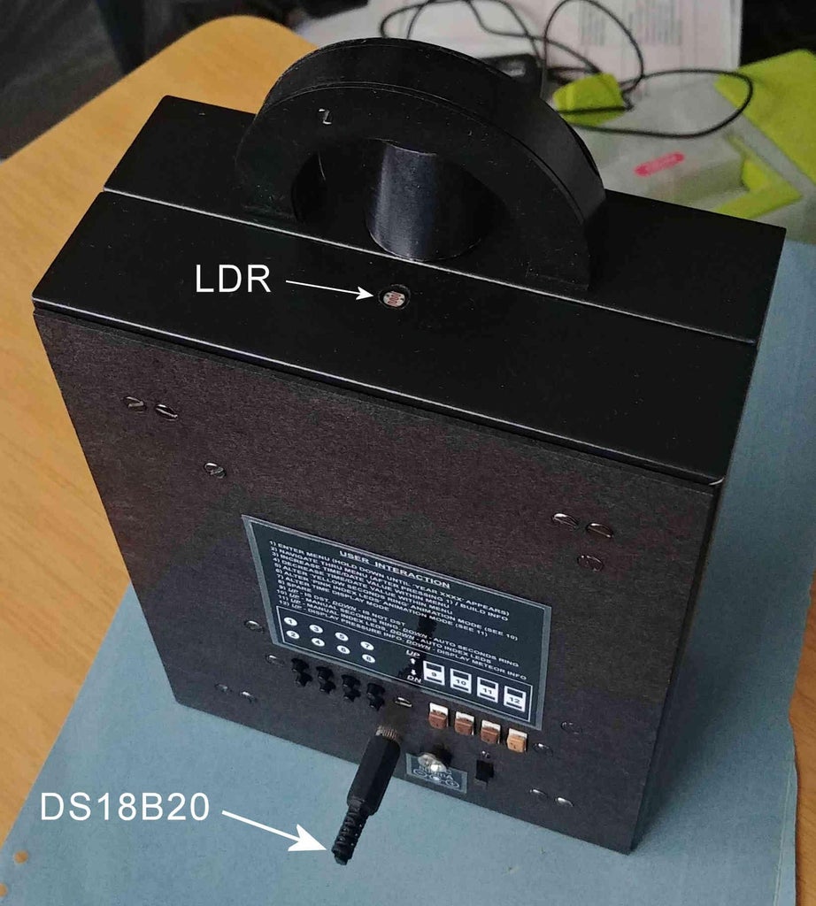
Note 2. In order to measure the ambient temperature correctly, the DS18B20 temperature sensor should be located outside of the photo frames (ie, away from any potential heat build up). In my case I have fitted it to a 3.5mm stereo jack plug, which in turn fits into 3.5mm stereo jack socket mounted to the clock's rear cover.
Note 3. In order to produce a uniform light intensity across the various 7-segment displays and yellow/pink/white discrete LEDs it may be necessary to alter the values of the following resistors:
- Rset of 8-digit, 7-segment MAX7219 module (Time display). Default value = 68k.
- Rset of 8-digit, 7-segment MAX7219 module (Date display). Default value = 68k.
- Rset of 8-digit, 7-segment MAX7219 module (Planet names display). Default value = 68k.
- Rset of MAX7219 chip (60 LEDs seconds ring). Default value = 22k.
- Rset of MAX7219 chip (Sun/Moon rise/set times displays). Default value = 27k.
- Rset of MAX7219 chip (Azimuth/Elevation positions displays). Default value = 27k.
- Rset of MAX7219 chip (Moon illumination/trend displays). Default value = 27k.
- Series resistors of white visibility LEDs 60 to 67. Default value = 1.5k.
- Series resistors of pink index LEDs 68 to 79. Default value = 750R.
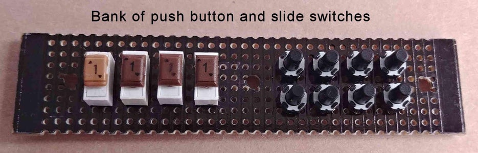
Note 4. For the numerous push button and toggle switches making up the circuit, I have mounted low profile versions of these onto a piece of veroboard (stripboard), and then mounted the veroboard to the clock's rear cover. You could of course simply fit panel mounted versions of these switches directly to the clock's rear cover.
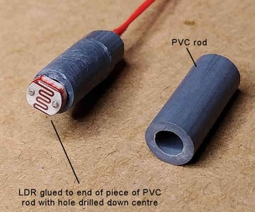
Note 5. The LDR is used to automatically adjust the brightness of the various displays/LEDs according to the ambient light intensity. For this reason the LDR should have an unrestricted view of the ambient light. I have glued the LDR to the end of a 6.5mm diameter, 16mm long piece of PVC rod with a 3mm diameter hole drilled through it. The rear photo frame has a 6.5mm diameter hole drilled into its top surface so that the PVC rod is a push fit into the hole. Once the PVC rod is pushed into the hole the top of the LDR should be flush with the top of the photo frame.
ADDITIONAL EXTRAS - You have the option to fit either one or both of the following:
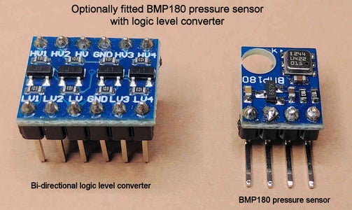
1) Optionally Fitted BMP180 Pressure Sensor
If you'd like to have the current pressure, together with the pressure trend over the previous 2 and 4 hours displayed, then fit the components within the square labelled 'Optional pressure sensor' on sheet 1 of the schematic Cosmic_Clock_schematic_Rev-A.pdf. Also ensure you add switch SW 0 as shown on sheets 1 and 2 of the schematic Cosmic_Clock_schematic_Rev-A.pdf. This switch enables you to select whether to display pressure information, or to display the next major meteor shower date on the 7-segment displays.
If you are not fitting the BMP180 pressure sensor then Switch SW 0 can be omitted as it will have no function.
2) Optionally Fitted (top photo frame mounted) Elevation and Azimuth Pointers to the planets/Sun/Moon
If you'd like to fit the top photo frame mounted elevation and azimuth pointers, that literally 'point' to the positions of the planets, Sun, and Moon in the sky, then it will be necessary to firstly construct the four PVC pieces as shown in STEP 13. Assuming you have constructed these four PVC pieces, then fit the thirteen 3mm yellow LEDs* within the square labelled 'Optional top mounted azimuth indicator using yellow LEDs', and the twelve 3mm red LEDs* within the square labelled 'Optional top mounted elevation indicator using red LEDs' on sheet 4 of the schematic Cosmic_Clock_schematic_Rev-A.pdf to the Elevation LED indicator and Azimuth LED indicator PVC pieces.
*Note, in a similar fashion to that in Step 7, file approximately 1mm off the (domed) top of the 13 yellow and 12 red LEDs to form flat topped LEDs, such that when the LEDs are fully inserted (from the inner side) into the 3.0mm diameter holes in the Azimuth LED indicator, and Elevation LED indicator (built in STEP 13), the top of the LEDs are just below (approximately 0.5mm) the outer side of these pieces. Once the LEDs have been filed to size, lightly run the flat topped LED surfaces across a piece of 300-400 Grit sanding sheet a few times to smooth the surface finish.
If you are not fitting the optional top photo frame mounted elevation and azimuth pointers, then these LEDs are simply omitted.
Attachments
Step 15: Configuring the Firmware for the ATmega644
The Arduino sketch Cosmic_Clock_ATmega644_rev_A.ino, and associated header file clock_planets.h are available for download at the bottom of this step, or from the following link:
https://drive.google.com/file/d/179JlRgvSD4ZlNzRk-48w29O9OkJH9aAJ/view?usp=sharing
Note, all references to line numbers in this step refer to Revision A of the ATmega644 sketch, ie, Cosmic_Clock_ATmega644_rev_A.ino. There is a minor update (Revision B) to this sketch in Step 21 which is now called Cosmic_Clock_ATmega644_rev_B.ino.
(Note, there are some unused variables in this sketch left over from a previous project, but they are not causing any issues, and so I have left them in.)
The Arduino libraries needed to compile this sketch are available from the following link:
https://drive.google.com/file/d/1SLccIRfF2JoLdcRl9m41fenxLmO1d2k7/view?usp=sharing
1) Latitude and Longitude of your location
It is necessary to input the Latitude and Longitude of your location in two separate places in the firmware:
In the Arduino sketch Cosmic_Clock_ATmega644_rev_A.ino, at lines 161and 162 alter the values of the Latitude and Longitude to match your location (default is Birmingham, UK). For the Longitude, West is negative, and East is positive. For the Latitude, North is positive, and South is negative.
In the file clock_planets.h, at lines 63 and 64, again alter the values of the Latitude and Longitude to match your location (default is Birmingham, UK). For the Longitude, West is negative, and East is positive. For the Latitude, North is positive, and South is negative.
Examples are given below:
a) For San Fransisco, USA
Alter lines 161 and 162 in Cosmic_Clock_ATmega644_rev_A.ino to become:
#define LONGITUDE -122.4194 // Longitude of current location (west is negative)
#define LATITUDE 37.7749 // Latitude of current location (north is positive)
Also alter lines 63 and 64 in clock_planets.h to become:
float lat = 37.7749; //Latitude of current location (North is positive)
float lonPlanet = -122.4194; // Longitude of current location (West is negative)
b) For Melbourne, Australia
Alter lines 161 and 162 in Cosmic_Clock_ATmega644_rev_A.ino to become:
#define LONGITUDE 145.0006 // Longitude of current location (west is negative)
#define LATITUDE -37.8101 // Latitude of current location (north is positive
Also alter lines 63 and 64 in clock_planets.h to become:
float lat = -37.8101; // Latitude of current location (North is positive)
float lonPlanet = 145.0006; // Longitude of current location (West is negative)
2) The time zone of your location relative to UTC (GMT)
It is necessary to input into the firmware the number of hours ahead or behind of UTC (GMT) your location is, both during Daylight Saving Time (DST), and when not in Daylight Saving Time (DST).
In the Arduino sketch Cosmic_Clock_ATmega644_rev_A.ino, at lines 310 and 311 alter the values of Time_Zone_DST and Time_Zone_NO_DST (default is Birmingham, UK).
Time_Zone_DST is, when in Daylight Saving Time, the numbers or hours ahead or behind of UTC (GMT) your location is. Negative numbers indicate that your location's time is behind UTC (GMT), whilst positive numbers indicate that your location's time is ahead of UTC (GMT).
Time_Zone_NO_DST is, when not in Daylight Saving Time, the numbers or hours ahead or behind of UTC (GMT) your location is. Negative numbers indicate that your location's time is behind UTC (GMT), whilst positive numbers indicate that your location's time is ahead of UTC (GMT).
Note, not every country employs Daylight Saving Time (eg, Japan), and in these cases the value of Time_Zone_DST and Time_Zone_NO_DST will be the same.
Examples are given below:
a) For San Fransisco, USA
#define Time_Zone_DST -7 // The numbers or hours ahead/behind UTC (GMT) time when in DST
#define Time_Zone_NO_DST -8 // The numbers or hours ahead/behind UTC (GMT) time when not in DST
b) For New York, USA
#define Time_Zone_DST -4 // The numbers or hours ahead/behind UTC (GMT) time when in DST
#define Time_Zone_NO_DST -5 // The numbers or hours ahead/behind UTC (GMT) time when not in DST
c) For Paris, France
#define Time_Zone_DST 2 // The numbers or hours ahead/behind UTC (GMT) time when in DST
#define Time_Zone_NO_DST 1 // The numbers or hours ahead/behind UTC (GMT) time when not in DST
d) For Melbourne, Australia
#define Time_Zone_DST 11 // The numbers or hours ahead/behind UTC (GMT) time when in DST
#define Time_Zone_NO_DST 10 // The numbers or hours ahead/behind UTC (GMT) time when not in DST
e) For Tokyo, Japan (Japan does not have Daylight Saving Time)
#define Time_Zone_DST 9 // The numbers or hours ahead/behind UTC (GMT) time when in DST
#define Time_Zone_NO_DST 9 // The numbers or hours ahead/behind UTC (GMT) time when not in DST
3) Optionally fitted (top photo frame mounted) Azimuth direction pointer (see STEP 13)
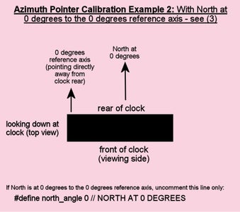
If you have fitted the optional (top photo frame mounted) Azimuth direction pointer, then you will need to specify the angle (to the nearest multiple of 30 degrees) of due North with respect to a line extending directly away from the rear of the photo frame (defined as the 0 degrees reference axis).
This is done by uncommenting ONLY ONE of the following 12 lines of code located between lines 402 and 413 in the Arduino sketch Cosmic_Clock_ATmega644_rev_A.ino:
//#define north_angle 0 // NORTH AT 0 DEGREES
//#define north_angle 30 // NORTH AT 30 DEGREES
//#define north_angle 60 // NORTH AT 60 DEGREES
//#define north_angle 90 // NORTH AT 90 DEGTREES
//#define north_angle 120 // NORTH AT 120 DEGREES
//#define north_angle 150 // NORTH AT 150 DEGREES
//#define north_angle 180 // NORTH AT 180 DEGREES
//#define north_angle 210 // NORTH AT 210 DEGREES
//#define north_angle 240 // NORTH AT 240 DEGREES
//#define north_angle 270 // NORTH AT 270 DEGREES
//#define north_angle 300 // NORTH AT 300 DEGREES
//#define north_angle 330 // NORTH AT 330 DEGREES
A compass app on your phone can help identify which direction North is.
Three orientation examples are given below:
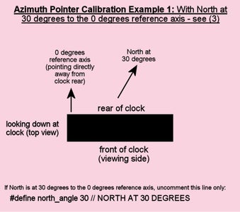
a) With due North at a 30 degree angle to the 0 degrees reference axis (see attached image titled 'Azimuth Pointer Calibration Example 1'), you would uncomment line170
//#define north_angle 30 // NORTH AT 30 DEGREES
to become:
#define north_angle 30 // NORTH AT 30 DEGREES
and so the 12 lines of code located between lines 402 and 413 would look like the following:
//#define north_angle 0 // NORTH AT 0 DEGREES
#define north_angle 30 // NORTH AT 30 DEGREES
//#define north_angle 60 // NORTH AT 60 DEGREES
//#define north_angle 90 // NORTH AT 90 DEGTREES
//#define north_angle 120 // NORTH AT 120 DEGREES
//#define north_angle 150 // NORTH AT 150 DEGREES
//#define north_angle 180 // NORTH AT 180 DEGREES
//#define north_angle 210 // NORTH AT 210 DEGREES
//#define north_angle 240 // NORTH AT 240 DEGREES
//#define north_angle 270 // NORTH AT 270 DEGREES
//#define north_angle 300 // NORTH AT 300 DEGREES
//#define north_angle 330 // NORTH AT 330 DEGREES
b) With due North at a 0 degree angle to the 0 degrees reference axis (see attached image titled 'Azimuth Pointer Calibration Example 2'), you would uncomment line
//#define north_angle 0 // NORTH AT 0 DEGREES
to become:
#define north_angle 0 // NORTH AT 0 DEGREES
and so the 12 lines of code located between lines 402 and 413 would look like the following:
#define north_angle 0 // NORTH AT 0 DEGREES
//#define north_angle 30 // NORTH AT 30 DEGREES
//#define north_angle 60 // NORTH AT 60 DEGREES
//#define north_angle 90 // NORTH AT 90 DEGTREES
//#define north_angle 120 // NORTH AT 120 DEGREES
//#define north_angle 150 // NORTH AT 150 DEGREES
//#define north_angle 180 // NORTH AT 180 DEGREES
//#define north_angle 210 // NORTH AT 210 DEGREES
//#define north_angle 240 // NORTH AT 240 DEGREES
//#define north_angle 270 // NORTH AT 270 DEGREES
//#define north_angle 300 // NORTH AT 300 DEGREES
//#define north_angle 330 // NORTH AT 330 DEGREES
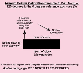
c) With due North at a 120 degree angle to the 0 degrees reference axis (see attached image titled 'Azimuth Pointer Calibration Example 3'), you would uncomment line
//#define north_angle 120 // NORTH AT 120 DEGREES
to become:
#define north_angle 120 // NORTH AT 120 DEGREES
Note, all references to line numbers in this step refer to Revision A of the ATmega644 sketch, ie, Cosmic_Clock_ATmega644_rev_A.ino. There is a minor update (Revision B) to this sketch in STEP 21 which is now called Cosmic_Clock_ATmega644_rev_B.ino.
https://www.instructables.com/Planet-Locating-Cosmic-Clock/
and so the 12 lines of code located between lines 402 and 413 would look like the following:
//#define north_angle 0 // NORTH AT 0 DEGREES
//#define north_angle 30 // NORTH AT 30 DEGREES
//#define north_angle 60 // NORTH AT 60 DEGREES
//#define north_angle 90 // NORTH AT 90 DEGTREES
#define north_angle 120 // NORTH AT 120 DEGREES
//#define north_angle 150 // NORTH AT 150 DEGREES
//#define north_angle 180 // NORTH AT 180 DEGREES
//#define north_angle 210 // NORTH AT 210 DEGREES
//#define north_angle 240 // NORTH AT 240 DEGREES
//#define north_angle 270 // NORTH AT 270 DEGREES
//#define north_angle 300 // NORTH AT 300 DEGREES
//#define north_angle 330 // NORTH AT 330 DEGREES
4) Enable/disable serial output for debugging
If you want to enable a serial output on the ATmega644 pins PD0 and PD1 for debugging purposes (eg, when using an electronic simulator package such as Proteus), then comment out line 228 and uncomment line 227 in the Arduino sketch Cosmic_Clock_ATmega644_rev_A.ino as follows:
#define serEn true
//#define serEn false
If you don't want to enable a serial output on Atmega644 pins PD0 and PD1 for debugging purposes (eg, when using an electronic simulator package such as Proteus), then comment out line 227 and uncomment line 228 in the Arduino sketch Cosmic_Clock_ATmega644_rev_A.ino as follows:
//#define serEn true
#define serEn false
5) 'Dot clock' time display mode options
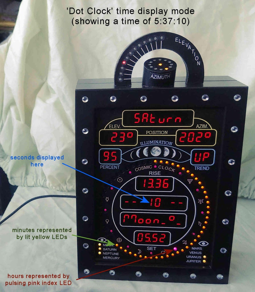
One of the time display modes (see Step 20) is called 'dot clock' mode. Here, the yellow ring of 60 LEDs is used to represent the minutes, whilst the 12 pink index LEDs are used to represent the hour (in 12 hour format).
In the Arduino sketch Cosmic_Clock_ATmega644_rev_A.ino, when in 'dot clock' mode, it is possible to select whether to display either
- the clock's seconds, or
- 'AM' or 'PM'
on the 7-segment display that would normally be showing the digital time (when not in 'dot clock' time display mode).
To make the selection, located at lines 307 and 308 in the Arduino sketch Cosmic_Clock_ATmega644_rev_A.ino, uncomment one of the following 2 lines below:
//boolean dot_clock_display_seconds = true; // displays seconds on the usual digital time display
//boolean dot_clock_display_seconds = false; // displays 'AM/PM' on the usual digital time display
For example, when in 'dot clock' time display mode, if you want to display the seconds on the 7-segment display that would normally be showing the digital time (when not in 'dot clock' time display mode), then the lines would look like:
boolean dot_clock_display_seconds = true; // displays seconds on the usual digital time display
//boolean dot_clock_display_seconds = false; // displays 'AM/PM' on the usual digital time display
Likewise, when in 'dot clock' time display mode, if you want to display either 'AM' or 'PM' on the 7-segment display that would normally be showing the digital time (when not in 'dot clock' time display mode), then the lines would look like:
//boolean dot_clock_display_seconds = true; // displays seconds on the usual digital time display
boolean dot_clock_display_seconds = false; // displays 'AM/PM' on the usual digital time display
6) Choosing favourite yellow seconds LED ring animations for automatic cycling through
The clock's current seconds are displayed in an animating style on the yellow ring of 60 LEDs. There are a total of 16 (or 18 if BMP180 is fitted) different animations to choose from. When switch SW 3 (on sheet 1 of the schematic Cosmic_Clock_schematic_Rev-A.pdf) is closed, your favourite 6 different animations are automatically cycled through, a different animation being selected every 10 minutes.
In order to change which 6 different favourite animations are selected, alter the number (from 0-15) after the words 'LED_RING_ANIMATION =' on lines 3590, 3601, 3612, 3623, 3634, and 3645 of the Arduino sketch Cosmic_Clock_ATmega644_rev_A.ino. To help you decide which LED_RING_ANIMATION modes to use it is best to cycle through them manually. By default the clock will start up in LED_RING_ANIMATION mode 0, and momentarily pressing switch SW 7 will advance the LED_RING_ANIMATION mode by 1.
The relevant 6 code sections to alter are below:
    if (minut1/10 == 0)
    {
       LED_RING_ANIMATION = 0;
    if (minut1/10 == 1)
    {
       LED_RING_ANIMATION = 1;
    if (minut1/10 == 2)
    {
       LED_RING_ANIMATION = 2;
    if (minut1/10 == 3)
    {
       LED_RING_ANIMATION = 3;
    if (minut1/10 == 4)
    {
       LED_RING_ANIMATION = 4;
    if (minut1/10 == 5)
    {
       LED_RING_ANIMATION = 6;
7) Optionally fitted BMP180 pressure sensor parameters
a) If you have fitted the optional BMP180 pressure sensor to the circuit (see Step 14), in order to display pressure readings on the Cosmic Clock, uncomment line 291, and comment out line 292 in the Arduino sketch Cosmic_Clock_ATmega644_rev_A.ino as follows:
#define bmp180En true // if bmp180 is fitted
//#define bmp180En false // if bmp180 is not fitted
Furthermore, if you have fitted the optional BMP180 pressure sensor, then the altitude above sea level (measured in meters) of the location of the Cosmic Clock needs to be inputted on line 280 of the Arduino sketch Cosmic_Clock_ATmega644_rev_A.ino. (The altitude above sea level, can, for example, be easily determined using a GPS app on your phone.)
For example, if you are located on the beach next to the sea, then line 280 would be:
float alt = 0.0;
Another example. If you are located at the top of Mount Everest, then line 280 would be:
float alt = 8848.0;
b) If you have not fitted the optional BMP180 pressure sensor to the circuit, uncomment line 292, and comment out line 291 in the Arduino sketch Cosmic_Clock_ATmega644_rev_A.ino as follows:
//#define bmp180En true // if bmp180 is fitted
#define bmp180En false // if bmp180 is not fitted
Furthermore, if you have not fitted the optional BMP180 pressure sensor, line 280 of the Arduino sketch Cosmic_Clock_ATmega644_rev_A.ino can be left unchanged.
Note, when incorporating the BMP180 pressure sensor into the circuit ensure you fit the components within the square labelled 'Optional pressure sensor' on sheet 1 of the schematic Cosmic_Clock_schematic_Rev-A.pdf. Also ensure you add switch SW 0 as shown on sheets 1 and 2 of the schematic Cosmic_Clock_schematic_Rev-A.pdf. This switch enables you to select whether to display pressure information, or to display the next major meteor shower date on the 7-segment displays.
8) Optionally fitted BMP180 pressure sensor related LED ring animation mode configuration
If the optional BMP180 pressure sensor has been fitted, then, the last (of 18) yellow LED ring animation modes will alternate every few seconds between showing the actual seconds of the clock, and showing the pressure trend over the last 2 and 4 hours. When displaying the actual seconds in this mode, the user has the option to have either a fixed seconds animation mode, or to have the seconds animation mode automatically cycle every 10 minutes through one of 6 animation modes. This is done by commenting/uncommenting out lines 304 and 305 in the Arduino sketch Cosmic_Clock_ATmega644_rev_A.ino as follows:
a) If you want to have a fixed seconds animation mode when alternately displaying the 2/4 hour pressure trend and displaying the actual seconds, lines 305 and 305 should be:
//boolean press_auto_cycle = true;
boolean press_auto_cycle = false;
Note, you can further choose which out of 6 possible seconds displaying animations you'd like to permanently display when alternating between showing the 2/4 hour pressure trend and showing the actual seconds. This is done by uncommenting 1 out of the 6 animations that are between lines 4334 and 4467 in the sketch 'Cosmic_Clock_ATmega644_rev_A.ino, and leaving the other 5 animations commented out. Eg, to select animation 2 to be displayed, the code should be as follows:
//"""""""""""""--

/*
Start of animation 1
   code......blah blah
End of animation 1
*/

//"""""""""""""--

Start of animation 2
   code......blah blah
End of animation 2

//"""""""""""""--

/*
Start of animation 3
   code......blah blah
End of animation 3
*/

//"""""""""""""--

/*
Start of animation 4
   code......blah blah
End of animation 4
*/

//"""""""""""""--

/*
Start of animation 5
   code......blah blah
End of animation 5
*/

//"""""""""""""--

/*
Start of animation 6
   code......blah blah
End of animation 6
*/

//"""""""""""""--
b) If you want to have an automatically cycling seconds animation mode when alternately displaying the 2/4 hour pressure trend and displaying the actual seconds, then lines 304 and 305 should be:
boolean press_auto_cycle = true;
//boolean press_auto_cycle = false;
Step 16: Configuring the Firmware for the ATmega328
The Arduino sketch Cosmic_Clock_ATmega328_rev_A.ino is available for download either at the bottom of this step, or from the following link:
https://drive.google.com/file/d/1G00A7tr2Zaoik-2vFHARVDhdcfX0S_Dv/view?usp=sharing
The Arduino libraries needed to compile this sketch are available from the following link:
https://drive.google.com/file/d/10eFiHlasKdxk4guU5K-Bj-wr9yN0QKJK/view?usp=sharing
1) Configuring how the hour is represented when in 'dot clock' time display mode
One of the time display modes (see Step 20) is called 'dot clock' mode. Here, the yellow ring of 60 LEDs is used to represent the minutes, whilst the 12 pink index LEDs are used to represent the hour (in 12 hour format).
When in 'dot clock' time display mode, you can choose how you would like the hour to be represented on the 12 pink index LEDs. This is done by uncommenting one of the following 6 lines (starting at line 40) in the Arduino sketch Cosmic_Clock_ATmega328_rev_A.ino:
//#define hour_dot 1 // NUMBER 1 hour-dot LED animation (see above)
//#define hour_dot 2 // NUMBER 2 hour-dot LED animation (see above)
//#define hour_dot 3 // NUMBER 3 hour-dot LED animation (see above)
//#define hour_dot 4 // NUMBER 4 hour-dot LED animation (see above)
//#define hour_dot 5 // NUMBER 5 hour-dot LED animation (see above)
//#define hour_dot 6 // NUMBER 6 hour-dot LED animation (see above)
The following describes how each of the 6 possible animations represent the hour being displayed:
- NUMBER 1 hour-dot LED animation. The current hour is indicated by lighting the current hour pink index LED at a fixed high brightness, whilst all the other 11 pink index LEDs are at a low brightness.
- NUMBER 2 hour-dot LED animation. The current hour is indicated by lighting the current hour pink index LED at a fixed high brightness, whilst all the other 11 pink index LEDs are unlit.
- NUMBER 3 hour-dot LED animation. The current hour is indicated by pulsing brighter (in sync with a change of second) at high brightness the current hour pink index LED, whilst all the other 11 pink index LEDs are at a low brightness.
- NUMBER 4 hour-dot LED animation. The current hour is indicated by pulsing brighter (in sync with a change of second) at high brightness the current hour pink index LED, whilst all the other 11 pink index LEDs are unlit.
- NUMBER 5 hour-dot LED animation. The current hour is indicated by pulsing dimmer (in sync with a change of second) at high brightness the current hour pink index LED, whilst all the other 11 pink index LEDs are at a low brightness.
- NUMBER 6 hour-dot LED animation. The current hour is indicated by pulsing dimmer (in sync with a change of second) at high brightness the current hour pink index LED, whilst all the other 11 pink index LEDs are unlit.
For example, if you'd like the hour to be represented by lighting the current hour pink index LED at a fixed high brightness, whilst all the other 11 pink index LEDs are unlit, then uncomment the 2nd line as follows:
//#define hour_dot 1 // NUMBER 1 hour-dot LED animation (see above)
#define hour_dot 2 // NUMBER 2 hour-dot LED animation (see above)
//#define hour_dot 3 // NUMBER 3 hour-dot LED animation (see above)
//#define hour_dot 4 // NUMBER 4 hour-dot LED animation (see above)
//#define hour_dot 5 // NUMBER 5 hour-dot LED animation (see above)
//#define hour_dot 6 // NUMBER 6 hour-dot LED animation (see above)
2) Adjusting the interval when cycling automatically through the various pink index LEDs animation modes
The ring of 12 pink index LEDs (adjacent to the yellow seconds ring of 60 LEDs) is used to provide visual indicators for every 5 seconds of time. This provides an aid in reading the seconds on the yellow seconds ring.
There are various animations to chose from for these 12 pink index LEDs. These can be selected manually, or can be set to automatically cycle through by closing switch SW 9 (on sheet 5 of the schematic Cosmic_Clock_schematic_Rev-A.pdf), a different animation being selected every 15 minutes - this time interval being user configurable. To adjust this time interval, in the Arduino sketch Cosmic_Clock_ATmega328_rev_A.ino, at line 52 adjust the value of 'const unsigned long TFT_Interval' to a suitable value from the default 900000 (15 minutes).
const unsigned long TFT_Interval = 900000; // 900000 milliseconds is the same as 15 minutes
Attachments
Step 17: Compiling the Arduino Sketches for the ATmega328 and ATmega644
The sketches for the ATmega644 and the ATmega328 have been compiled using Arduino IDE v1.8.19. I have not tested any other IDE versions.
1) Compiling the Arduino sketch for the ATmega328
When compiling for the ATmega328, in the Arduino IDE select 'Arduino Uno' as the Board in the Tools>Board>Arduino AVR Boards menu item, and, having opened the Cosmic_Clock_ATmega328_rev_A.ino sketch, export the compiled hex file by selecting 'Export compiled Binary' from the Sketch menu.
2) Compiling the Arduino sketch for the ATmega644
When compiling for the ATmega644 you will first need to install the 'MightyCore' Arduino core package that adds support for the ATmega644 (which the native Arduino IDE doesn't have). There are instructions on the MightyCore webpage on how to do this at:
In summary, you add the URL below to the 'Additional Boards Manager URLs' entry under the 'Settings' tab of File>Preferences menu item:
https://mcudude.github.io/MightyCore/package_MCUdude_MightyCore_index.json
Then go to Tools>Board>Boards Manager menu item, and wait for the platform indexes to finish downloading. Scroll down until you see the 'MightyCore' entry and click on it. Click 'Install'. Once installation is complete, close the 'Boards Manager' window.
Following successful installation of 'MightyCore', open the Tools>Board>MightyCore menu item and select ATmega644. Then, from the 'Tools' menu select the following entries:
- Clock: External 16MHz
- BOD: BOD disabled
- EEPROM: EEPROM retained
- Compiler LTO: Enabled
- Varient: 644/644A (if you have an ATmega644), or 644P/644PA (if you have an ATmega644P)
- Pinout: Standard pinout
- Bootloader: No bootloader
Now, open the Cosmic_Clock_ATmega644_rev_A.ino sketch, and export the compiled hex file by selecting 'Export compiled Binary' from the Sketch menu.
Step 18: Programming the ATmega328 and ATmega644 With the Compiled Hex Files
The free PC program AVRDUDESS will be used to program the ATmega328 and ATmega644 with the compiled hex files (from the previous step) using an Arduino Uno that has the 'ArduinoISP' sketch uploaded to it. (The 'ArduinoISP' sketch can be found in the File>Examples>ArduinoISP menu item of the Arduino IDE.)
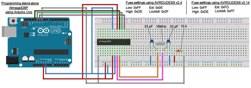
1) Programming the Standalone ATmega328
For programming the ATmega328, wire up the Arduino Uno (with the 'ArduinoISP' sketch loaded onto it) to the ATmega328 (that's on a breadboard together with a 16Mhz crystal, 2x 33pF capacitors, and a 10k resistor) according to the attached image.
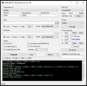
With the Arduino Uno connected to a PC via a USB cable, run the AVRDUDESS v2.14 program.
Basic AVRDUDESS Usage for the ATmega328 (see attached picture)
- Towards the top left of the AVRDUDESS window, select the appropriate Com Port, in the Port (-P) drop down selection box, that the Arduino Uno has been allocated by the PC. This can be checked by opening up the Device Manager on the PC, and expanding the Ports (COM & LPT) section.
- In the Programmer (-c) drop down selection box at the top left, select Arduino.
- In the Baud rate (-b) box, type in 19200.
- Click the MCU (-p) Detect button at the top right, and ensure that ATmega328P displays as being detected in the MCU (-p) drop down box.
- In the Fuses & lock bits section at the middle right of the AVRDUDESS window:
Type 0xFF in the text box to the right of the letter L. (L is short for Low).
Type 0xDE in the text box to the right of the letter H. (H is short for High).
Type 0xFD in the text box to the right of the letter E. (E is short for Extended).
Type 0xFF in the text box to the right of the letters LB. (LB is short for Lock Bit).
- Click the Write button to the right of the Low text box. Confirm that the Low, High, and Extended fuses have been successfully written to the chip by noting the word SUCCESS in the text console at the bottom quarter of the AVRDUDESS window.
- Likewise, click the Write button to the right of the Lock Bit text box. Confirm that the Lock Bit fuse have been successfully written to the chip by noting the word SUCCESS in the text console at the bottom quarter of the AVRDUDESS window.
- In the Flash section of the AVRDUDESS window click the small box with 3 dots in it to open a window to allow you to select the .hex file compiled for the ATmega328. Select the ATmega328 compiled .hex file, and ensure that the radio button to the left of the word Write in the Flash section has a dot in it. Then click the button labelled Go in the Flash section. You should now see the the .hex file uploading to the ATmega328 as confirmed in the text console section. Verify that the .hex file has been successfully uploaded to the ATmega328 by checking the text console.
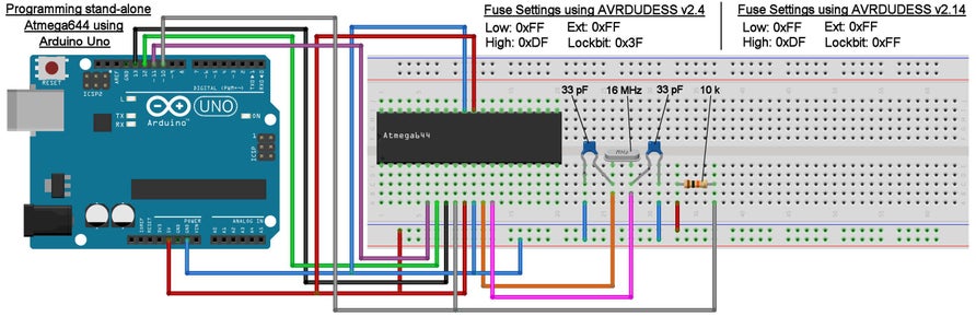
2) Programming the Standalone ATmega644
For programming the ATmega644, wire up the Arduino Uno (with the 'ArduinoISP' sketch loaded onto it) to the ATmega644 (that's on a breadboard together with a 16Mhz crystal, 2x 33pF capacitors, and a 10k resistor) according to the attached image.
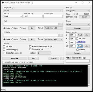
With the Arduino Uno connected to a PC via a USB cable, run the AVRDUDESS v2.14 program.
Basic AVRDUDESS Usage for the Atmega644 (see attached picture)
- Towards the top left of the AVRDUDESS window, select the appropriate Com Port, in the Port (-P) drop down selection box, that the Arduino Uno has been allocated by the PC. This can be checked by opening up the Device Manager on the PC, and expanding the Ports (COM & LPT) section.
- In the Programmer (-c) drop down selection box at the top left, select Arduino.
- In the Baud rate (-b) box, type in 19200.
- Click the MCU (-p) Detect button at the top right, and ensure that ATmega644 displays as being detected in the MCU (-p) drop down box.
- In the Fuses & lock bits section at the middle right of the AVRDUDESS window:
Type 0xFF in the text box to the right of the letter L. (L is short for Low).
Type 0xDF in the text box to the right of the letter H. (H is short for High).
Type 0xFF in the text box to the right of the letter E. (E is short for Extended).
Type 0xFF in the text box to the right of the letters LB. (LB is short for Lock Bit).
- Click the Write button to the right of the Low text box. Confirm that the Low, High, and Extended fuses have been successfully written to the chip by noting the word SUCCESS in the text console at the bottom quarter of the AVRDUDESS window.
- Likewise, click the Write button to the right of the Lock Bit text box. Confirm that the Lock Bit fuse have been successfully written to the chip by noting the word SUCCESS in the text console at the bottom quarter of the AVRDUDESS window.
- In the Flash section of the AVRDUDESS window click the small box with 3 dots in it to open a window to allow you to select the .hex file compiled for the ATmega644. Select the ATmega644 compiled .hex file, and ensure that the radio button to the left of the word Write in the Flash section has a dot in it. Then click the button labelled Go in the Flash section. You should now see the the .hex file uploading to the ATmega644 as confirmed in the text console section. Verify that the .hex file has been successfully uploaded to the ATmega644 by checking the text console.
Step 19: Final Assembly - Fitting Everything Together
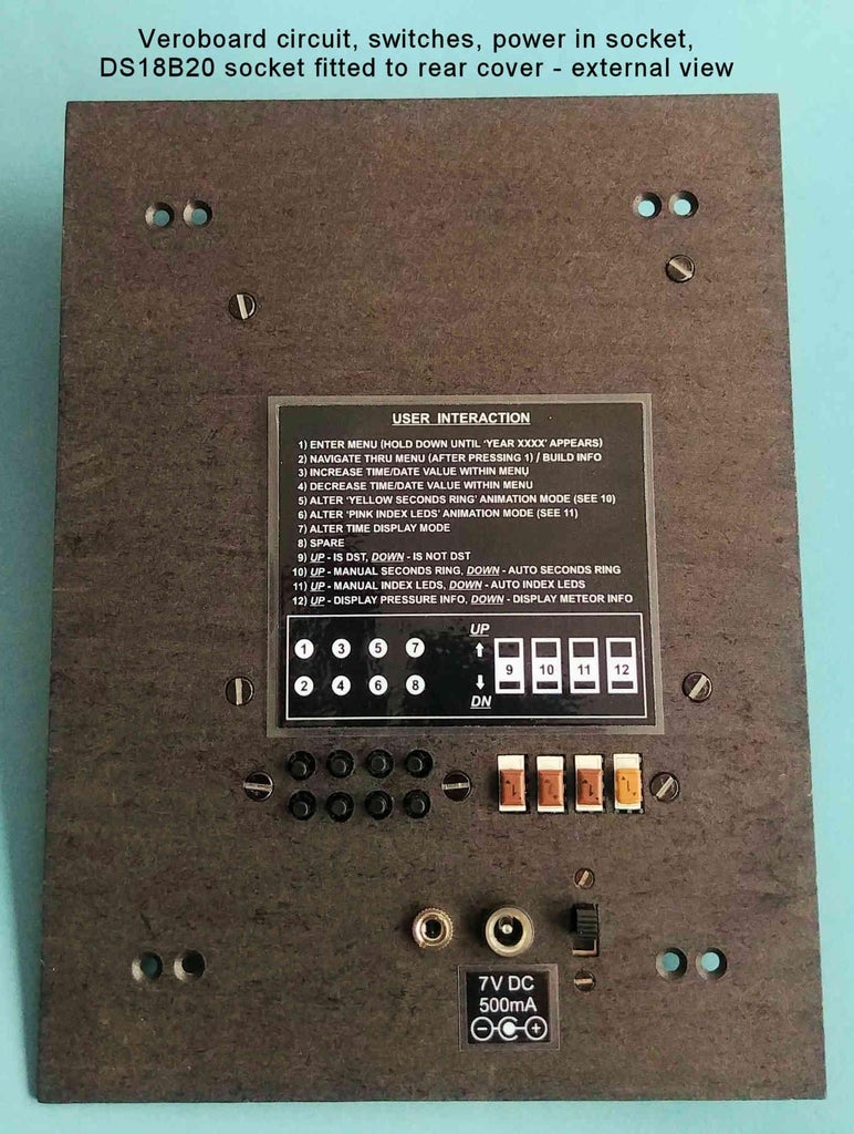
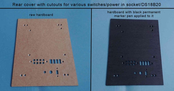
1) Make appropriately sized cutouts/holes in the rear cover to allow the veroboard circuit, various switches, power in socket, and DS18B20 to attach to it.
2) Run a black permanent marker pen over the visible surface of the rear cover to turn it black.
3) Separate the two front and rear photo frames.
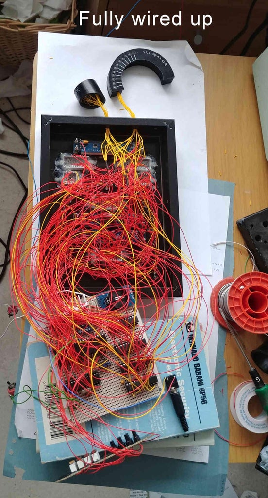
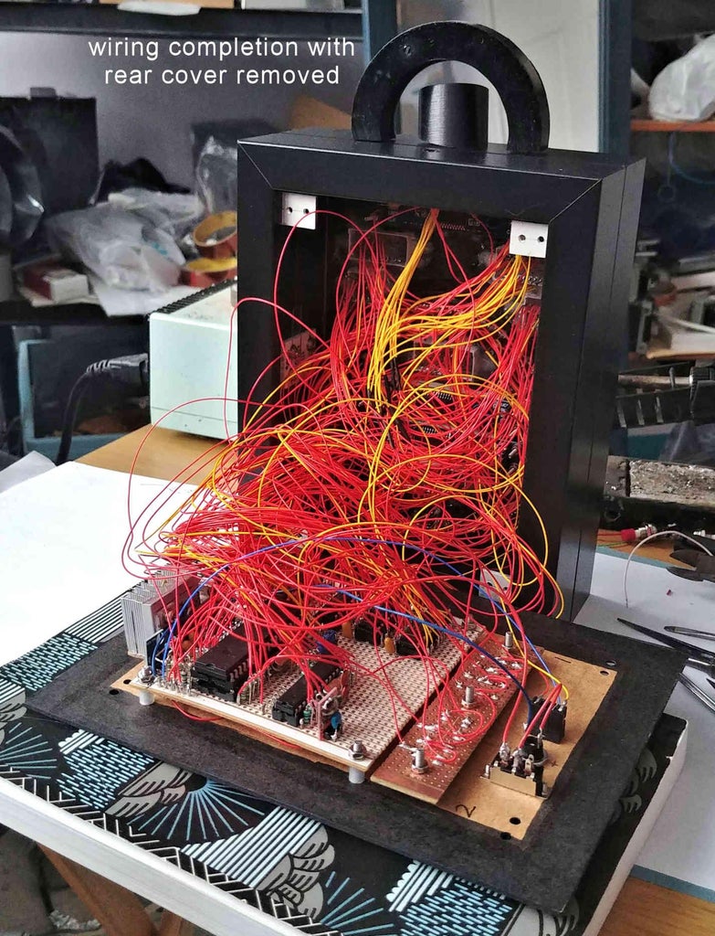
4) Make all electrical connections between the veroboard circuit, LEDs, 7-segment displays, switches, and DS18B20.
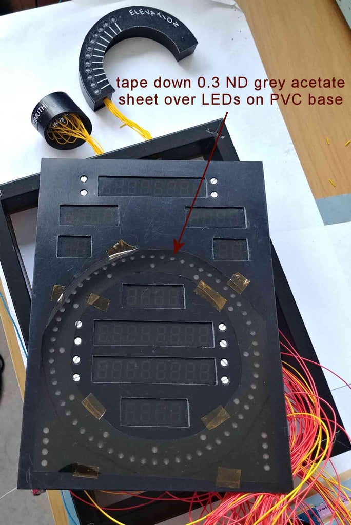
5) Cut a piece out of the 0.3 ND grey acetate sheet of appropriate size such that covers just the pink, white, and yellow LEDs in the PVC base. This will act as a contrast enhancing filter for the LEDs in bright ambient light conditions. Tape down this acetate sheet onto the PVC base to secure it in place.
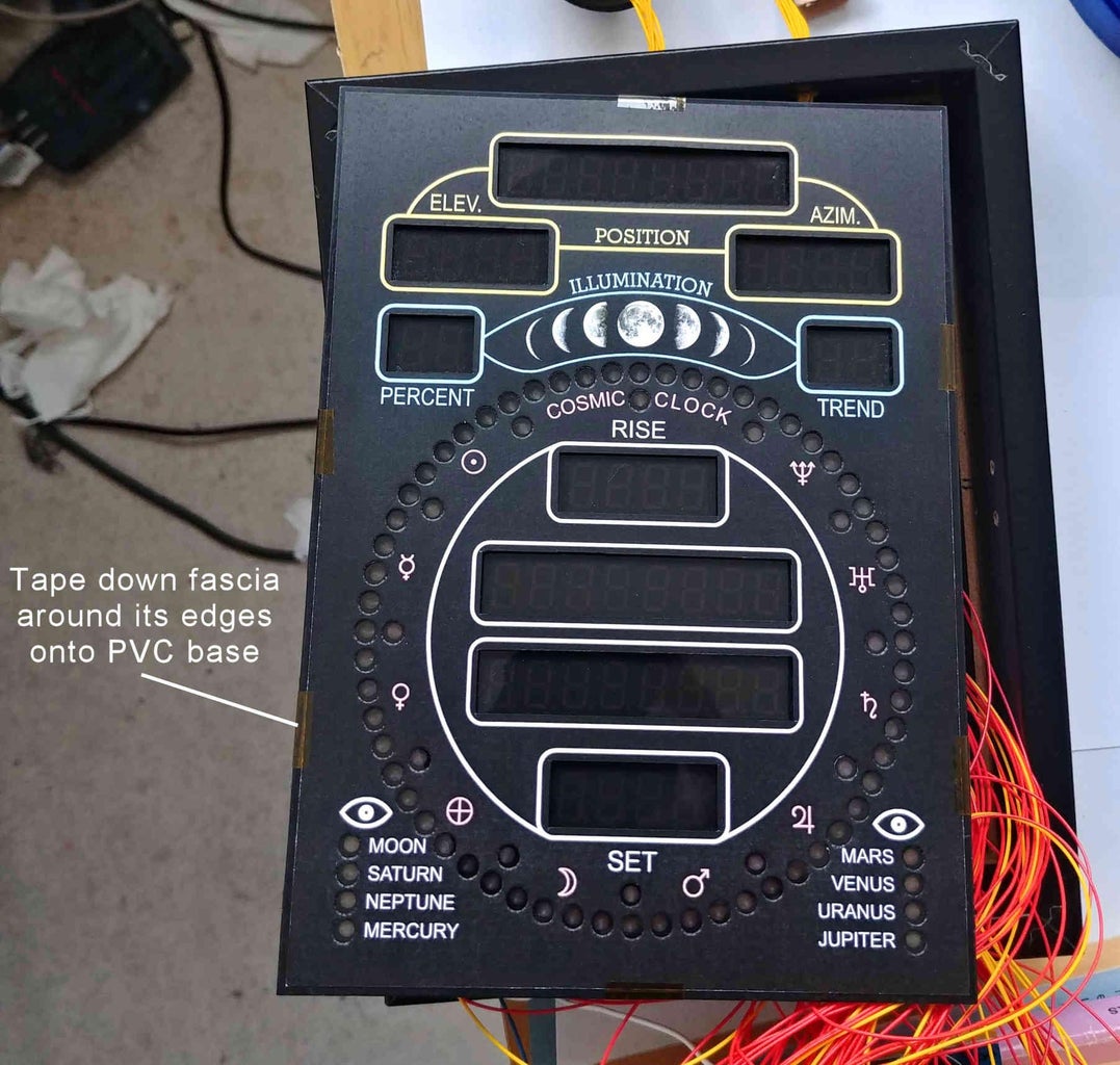
6) Cut the paper fascia to a size 1-2mm smaller around its perimeter than the PVC base. Tape down the fascia around its edges onto the PVC base to secure it in place.
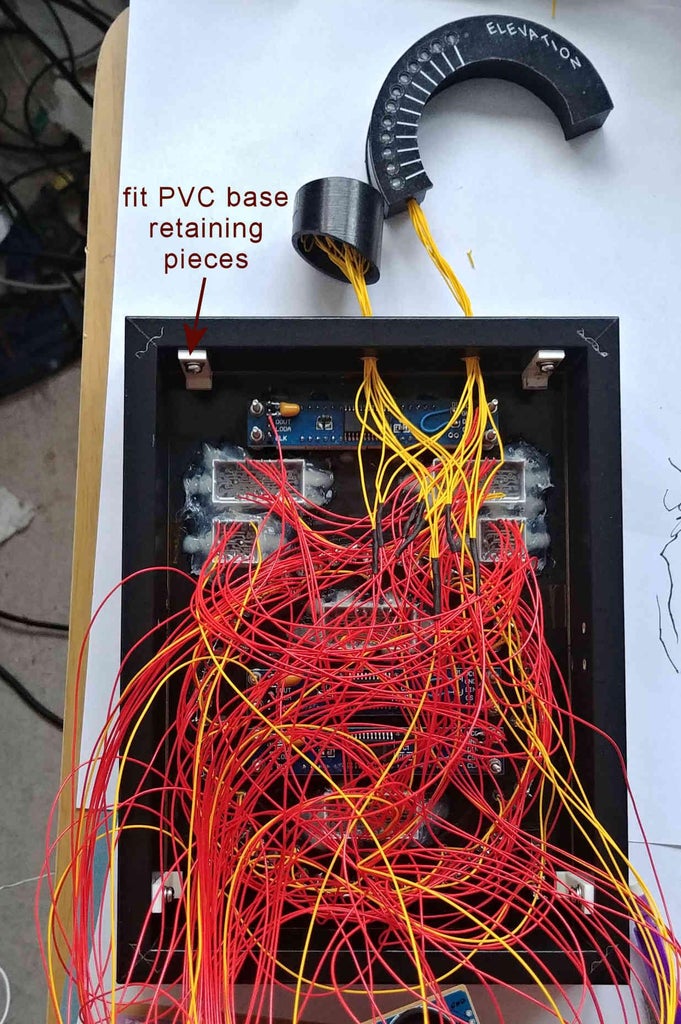
7) Slot the PVC base into the front photo frame, and secure it in place using the PVC base retaining pieces from Step 11.
8) Rejoin the front and rear photo frames together.
9) Attach the veroboard circuit, switches, DS18B20, and power in socket to the rear cover.
10) Secure the top frame mounted Elevation and Azimuth pointers in place either using a little Blu Tack, or glue.
11) Stick some self adhesive gems around the front photo frame surface to enhance its look.
12) Print at 100% size (not 'fit to page') the attached file cosmic_clock_rear_label.pdf onto an A4 white sheet of paper. Choose which of the 4 User Interactions you prefer, and cut it out of the paper. Laminate this chosen User Interaction paper. Fit it to the rear cover using a little Blu Tack.
Attachments
Step 20: Cosmic Clock User Guide
1) Setting the Time and Date
- Hold down push button switch SW 6 until "YEAR.xxxx" appears on the display.
- Use push button switch SW 4 to increase, or push button switch SW 5 to decrease the year as appropriate.
- Press push button switch SW 1 such that "MONTH.xx" appears on the display.
- Use push button switch SW 4 to increase, or push button switch SW 5 to decrease the month as appropriate.
- Press push button switch SW 1 such that "DAY.xx" appears on the display.
- Use push button switch SW 4 to increase, or push button switch SW 5 to decrease the day as appropriate.
- Press push button switch SW 1 such that "HOUR.xx" appears on the display.
- Use push button switch SW 4 to increase, or push button switch SW 5 to decrease the hour as appropriate.
- Press push button switch SW 1 such that "MIN.xx" appears on the display.
- Use push button switch SW 4 to increase, or push button switch SW 5 to decrease the minute as appropriate.
- Press push button switch SW 1 to confirm the time/date settings. The clock will now be re-set, starting at 0 seconds.
2) Altering Time Display Mode
To cycle through the 12 possible time display modes, momentarily press push button switch SW 8 whilst the time is being displayed. Each button press will move onto the next time display mode as follows (the last time display mode wrapping back around to the first one):
- 24 hour clock showing seconds, with hyphen as hour/minute/second separator (default).
- 24 hour clock showing seconds, with decimal point as hour/minute/second separator.
- 24 hour clock without showing seconds, with hyphen as hour/minute separator.
- 24 hour clock without showing seconds, with decimal point as hour/minute separator.
- 12 hour clock (without hour leading zero) without showing seconds, with hyphen as hour/minute separator.
- 12 hour clock (without hour leading zero) without showing seconds, with decimal point as hour/minute separator.
- 12 hour clock (with hour leading zero) without showing seconds, with decimal point as hour/minute separator, and AM or PM letters displaying at far right (to indicate AM or PM).
- 12 hour clock (without hour leading zero) without showing seconds, with hyphen as hour/minute separator, and A or P letter displaying at far right (to indicate AM or PM).
- 12 hour clock (without hour leading zero) without showing seconds, with decimal point as hour/minute separator, and A or P letter displaying at far right (to indicate AM or PM).
- 12 hour clock (without hour leading zero) showing seconds, with hyphen as hour/minute separator.
- 12 hour clock (without hour leading zero) showing seconds, with decimal point as hour/minute separator.
- A 12 hour 'dot clock'. Here, the yellow ring of 60 LEDs is used to represent the minutes. The topmost yellow LED (at the 12 o'clock position) representing zero minutes, increasing minutes being represented by increasingly (clockwise) lit LEDs. The pink ring of 12 LEDs is used to represent the hour (in 12 hour format). The topmost pink LED (at the 12 o'clock position) representing 0/12 hours, increasing hours being represented by a single lit LED progressing in a clockwise fashion. (See Step 16 on how to configure this.) In this mode you can choose to display (on the 7-segment display that would normally display the digital time) either the seconds, or to display AM or PM. (See Step 15 on how to configure this.)
3) Manual/Automatic Altering of Yellow Seconds-Ring Animation Modes
The clock's current seconds are displayed in an animating style on the yellow ring of 60 LEDs. These various animation styles (modes) can be altered both manually and automatically.
a) Manually altering
To manually cycle through the various yellow seconds-ring animation modes, firstly ensure that switch SW 3 is in the open position, then, momentarily press push button switch SW 7. Each push button press will move onto the next seconds-ring animation mode, the last animation mode wrapping back around to the first one.
Note, some of the animation modes directly represent the actual seconds of the current time, whilst other animation modes are for aesthetics only, and do not represent the actual seconds of the current time.
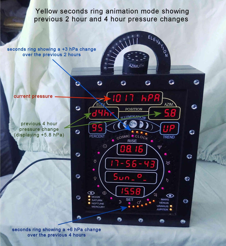
If the optional BMP180 pressure sensor has been fitted, then, the last two seconds-ring animation modes represent the previous 2 hours and previous 4 hours pressure trends. In both these animation modes, the 0 seconds LED, (at the 12 o'clock position) signifying a 0 hPa pressure change for the last 2 hours, and the 30 seconds LED, (at the 6 o'clock position) signifying a 0 hPa pressure change for the last 4 hours are always lit. Positive pressure changes are then indicated by lighting successive LEDs to the right of an imaginary vertical line joining the 0 and 30 seconds LEDs, each lit LED representing a 1 hPa change. Negative pressure changes are indicated by lighting successive LEDS to the left of an imaginary vertical line joining the 0 and 30 seconds LEDs, each lit LED representing a 1hPa change. The difference between these (last two seconds-ring) animation modes is that in the second to last animation mode, the pressure trend over the previous 2 and 4 hours is permanently displayed, whilst in the last animation mode the 2 and 4 hour pressure trends alternately cycle with displaying either a fixed or a continually rotating real time seconds animation. (See Step 15 on how to configure this.)
b) Automatic alteration
To automatically cycle between 6 yellow seconds-ring animation modes, set switch SW 3 to the closed position. The yellow seconds-ring animation mode will now automatically change every 10 minutes of the hour without any further user interaction.
4) Manual/Automatic Altering of Pink Index-Ring animation modes
The ring of 12 pink index LEDs (adjacent to the yellow seconds ring of 60 LEDs) are used to provide visual indicators for every 5 seconds of time. This provides an aid in reading the seconds on the yellow seconds ring. How these LEDs animate over time can be altered both manually and automatically.
a) Manually altering
To manually cycle through the various pink index-ring animation modes, firstly ensure than switch SW 9 is in the open position, then, momentarily press push button switch SW 10. Each push button press will move onto the next index-ring animation mode, the last animation mode wrapping back around to the first one.
Note, some of the animation modes (eg, the first one - known as heart beat mode) are triggered by the time's changing of the second, whilst other animation modes are not triggered by the time's changing of the second.
b) Automatic alteration
To automatically cycle between the various pink index-ring animation modes, set switch SW 9 to the closed position. The pink index-ring animation mode will now automatically change every 15 minutes (user configurable - see Step 16) without any further user intervention.
5) Daylight Saving Time Switch
The clock does not automatically adjust for Daylight Saving Time (assuming your country has Daylight Saving Time). You must manually adjust the clock for the correct time when Daylight Saving Time begins and ends throughout the year. As well as manually adjusting the time, when it is Daylight Saving Time (eg, typically between March and October in the USA), you must also set switch SW 2 to the closed position. If it is not Daylight Saving Time then you must set switch SW 2 to the open position. (See Step 15 on inputting into the Arduino sketch the number of hours ahead/behind GMT your location is when in/not in Daylight Saving Time.) If your country does not have Daylight Saving Time (eg, Japan), then you can set slide switch SW 2 to either the open or closed position, or even omit it completely.
6) Optional - Displaying Next Meteor Shower, or Current Pressure/Pressure Trend information
If the optional BMP180 pressure sensor has been fitted in the circuit you have the option of either displaying the current pressure together with the pressure trend over the last 2 and 4 hours, or displaying the approximate date of the next major meteor shower. If switch SW 0 is in the closed position then the current pressure together with the pressure trend over the last 2 and 4 hours will be displayed. If switch SW 0 is in the open position then the approximate date of the next major meteor shower will be displayed instead.
If the optional BMP180 pressure sensor has NOT been fitted in the circuit then the date of the next major meteor shower will always be displayed, regardless of whether switch SW 0 is in the open or closed position. In fact, if the optional BMP180 pressure sensor has not been fitted, then switch SW 0 can be omitted completely.
7) Displaying a short message together with a little animation
When the clock is showing the time, if you hold down switch SW 1 for about 1 second and then release it, the clock will display the build date of the clock together with a little animation on the yellow seconds ring of 60 LEDs. This message/animation will appear for a few seconds, and then the clock will revert back to displaying the time.
If you want to alter the displayed build date then alter the text between the inverted commas at lines 6158 to 6174 in the Arduino sketch Cosmic_Clock_ATmega644_rev_A.ino.
Step 21: Optional ATmega644 Firmware Update
The optional Revision B of the ATmega644 Arduino sketch Cosmic_Clock_ATmega644_rev_B.ino (downloadable at the bottom of this step) has the following minor changes compared to Revision A in Step 15 (Cosmic_Clock_ATmega644_rev_A.ino):
1) When displaying the Planet's name, you now have the option (or not) of alternating it with displaying an abbreviated form of its name, together with displaying the Planet's current magnitude. This is accomplished by commenting out either line 329 or line 330 in the Arduino sketch Cosmic_Clock_ATmega644_rev_B.ino.
To alternate the Planet's name with its magnitude comment out line 330 so that lines 329 and 330 look like the following:
boolean mag_show = true; // show the planet's magnitude, together with....
//boolean mag_show = false; // does NOT show the planet's magnitude, together with....
To NOT alternate the Planet's name with its magnitude comment out line 329 so that lines 329 and 330 look like the following:
//boolean mag_show = true; // show the planet's magnitude, together with...
boolean mag_show = false; // does NOT show the plSW3anet's magnitude, together with...
The attached animated gif shows how the alternating Planet's magnitude looks like.
2) Closing switch SW3 now auto cycles through all the (non atmospheric pressure related) seconds ring animations at a user configurable interval, as opposed to just 6 animations at a fixed interval of every 10 minutes. The default configurable interval between seconds ring animation changes is set to 5 minutes. To alter this interval change the number at the end of line 326. This number is the interval in milliseconds.
const unsigned long Seconds_Interval = 300000; // 300000 milliseconds is 5 minutes
Attachments

This is an entry in the
Anything Goes Contest